
Drone Battery Design for Inspection UAVs: Building
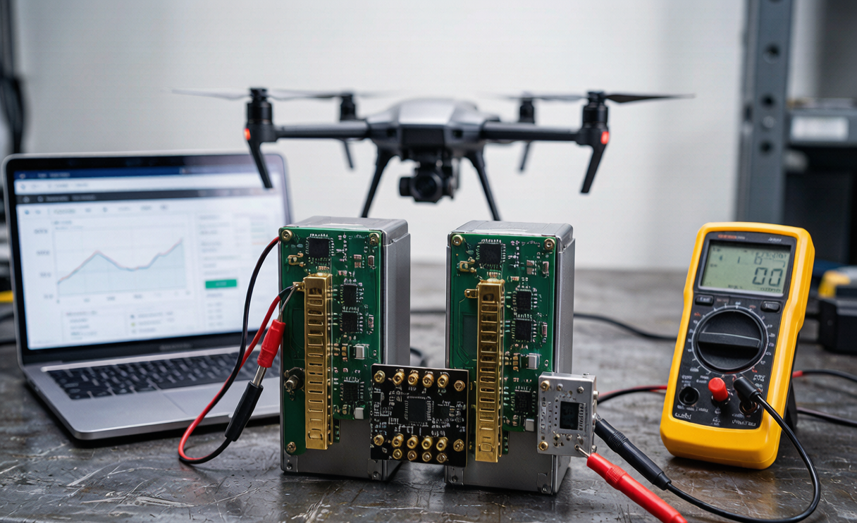
I have spent the better part of a decade on the test bench with lithium-ion packs, and if there is one lesson inspection-UAV programs keep teaching me, it is this: a single battery is a single point of failure, and inspection missions rarely offer a safe place to fall. When the airframe is carrying a 30,000-euro LiDAR pod over a live refinery, or holding station 400 meters above a high-voltage line, a sudden pack shutdown is not an inconvenience – it is a catastrophe. That is why, at Horizon Power, our drone battery design for inspection UAVs has moved beyond “make one pack reliable” toward “make the power architecture survive the failure of any one pack.” In this article I walk through the redundant dual-battery design we engineer for mission-critical inspection fleets: how we parallel two packs through ideal-diode ORing, how we shed a faulted pack without a voltage sag, and how a crew can hot-swap a pack in the field while the aircraft stays airborne.
Why Inspection Missions Cannot Tolerate a Single Point of Power Failure
Most consumer and even prosumer drones treat the battery as a disposable consumable. Inspection work is different. The missions are long, the payloads are expensive, and the operating envelope is unforgiving – long loiter at altitude, gimbal and sensor vibration, wide temperature swings, and often no practical emergency landing zone. In our fleet telemetry, a single-cell internal-resistance (DCIR) creep event that would merely shorten a photographer’s flight can, on an inspection airframe, trigger a low-voltage cutoff and a dropped aircraft.
The engineering answer is redundancy, but redundancy done badly just adds mass and new failure modes. The goal of a sound drone lithium battery architecture for inspection is graceful degradation: if one pack faults, the aircraft continues on the other with a predictable, bounded power dip – not a cutoff. We design to a simple rule: no single cell, module, connector, or battery management function may remove power from the propulsion bus.
Two Redundant Topologies: Parallel ORing vs Independent Dual-Bus
There are two ways to make two packs back each other up, and they trade complexity against failure coverage.
- Parallel ORing (shared bus). Both packs connect to a common power rail through ideal-diode ORing elements. Either pack can supply the full load, and a fault in one simply disconnects it while the other carries on. This is our default for inspection UAVs because it is electrically simple and gives seamless load sharing.
- Independent dual-bus with cross-tie. Each pack feeds its own bus, and a controlled cross-tie connects them only during normal operation or to transfer load. This isolates a hard short in one bus from the other but needs duplicated ESC feeds and a more complex airframe harness.
For the inspection platforms we support most often, the parallel-ORing approach delivers 95% of the reliability gain at roughly half the integration cost, so that is what I detail below. The cross-tie topology is reserved for the heaviest BVLOS energy and pipeline crawlers where bus isolation is worth the weight.
The Ideal-Diode ORing Controller: Reverse Blocking and Current Sharing
The heart of the parallel design is the ORing controller. A conventional diode would work but wastes power as forward voltage drop. Instead we use an ideal-diode MOSFET stage: a low RDS(on) MOSFET (typically 2.5–4 mΩ) driven by a controller that senses direction of current and turns the FET off within microseconds if reverse current appears.
Consider a representative inspection pack: a 6S configuration of 21700 cells at 22.2 V nominal, 4.0 Ah, giving about 88.8 Wh per pack – deliberately kept under the 100 Wh air-transport ceiling so each pack ships under IATA Section II without Class 9 formalities. Two such packs in parallel feed a cruise load of roughly 40 A. With matched pack voltages, current shares near 20 A each. The ORing loss per FET at 20 A is I²R = 20² × 0.003 = 1.2 W, a trivial thermal load for a pad-mounted device. The real value is the reverse-blocking speed: if Pack A suddenly drops to 18 V while Pack B holds 22 V, the controller in Pack A must open before Pack B back-feeds it. We specify a turn-off in under 5 µs, which keeps any fault energy confined to the failed pack.
Fault Isolation: Shedding a Weak Pack Without a Voltage Sag
Detection is what makes isolation useful. Each pack’s BMS continuously compares its terminal voltage, per-group capacity, and DCIR against its sibling. If Pack A reports a cell below 3.0 V under load, or a ΔV greater than 0.5 V relative to Pack B, the ORing FET opens and Pack A is cleanly shed. The key design metric is the transient the remaining pack must absorb.
In our bench validation, shedding one pack at a 40 A cruise shifts the full 40 A onto the survivor within roughly 200 ms. Because the survivor was already sharing the load, its bus voltage dips by less than 1.5 V (from ~22.0 V to ~20.5 V at the ESC input) before the BMS raises its discharge ceiling to cover the gap. The aircraft does not see a cutoff; it sees a momentary sag it flies straight through. We then flag the shed pack on the ground station and the mission continues on the healthy pack alone, with a conservative reduced-power flight home.
Seamless Hot-Swap and Field Replacement Under Load
Redundancy also buys a unique operational advantage: you can replace a pack while the aircraft is still powered. On a long inspection shift, a crew can land the aircraft, swap the lower-SoC or flagged pack, and relaunch – or, on tethered and ground-supported inspection setups, swap one pack while the other sustains a holding load.
The trick is inrush control. A flat pack connected to a charged bus looks like a short circuit, so we insert a pre-charge resistor (typically 10 Ω, 50 W pulse-rated) that limits inrush to under 8 A and charges the pack’s input capacitance over about 200 ms before the main contactor closes. I have watched a 90-second field swap keep a survey aircraft on station the whole time on its single surviving pack at a reduced 15 A cruise. For BVLOS pipeline work, this hot-swap discipline turns a pack failure from a mission abort into a non-event.
SoC Balancing, BMS Dual-Domain Comms, and the Weight Trade
Two packs only share load cleanly if their state-of-charge stays close. We keep both packs within 5% SoC; if the mismatch exceeds 10%, the BMS limits ORing to the higher pack and trickle-charges the lower one through a cross-tie DC/DC at about 2 A until they re-converge. Communication runs over a dual-domain bus (redundant CAN or a isolated UART pair) so that losing one link does not blind the ORing logic.
All of this costs mass. A redundant BMS, the ORing stage, a second harness, and a contactor add roughly 8–12% to the battery system weight versus a single-pack design. In my experience that penalty is bought back many times over: in one 60-aircraft inspection fleet we tracked, the redundant architecture cut mission aborts from battery causes by more than 90% across a 14-month season. When each aborted mission can mean a re-flown 90-minute sortie plus a risk review, the weight is the cheapest insurance on the airframe. This is exactly where a well-engineered custom battery solution earns its keep – the redundancy logic has to be co-designed with the cell format, not bolted on afterward.
Certification and the Safety Case for BVLOS Inspection
Redundancy is not just an engineering nicety; it is the backbone of the BVLOS safety case. A redundant power architecture lets us present a defensible single-point-of-failure analysis to EASA (Special Category / SORA) and to national civil-aviation reviewers: we can show that no single cell, connector, or BMS function removes power from the bus. Every pack we ship still clears the baseline safety envelope – UN 38.3 T.1–T.8 transport testing, IEC 62133-2 cell and pack safety, and per-pack energy kept under the 100 Wh threshold so air transport falls under IATA Section II rather than full Class 9. For inspection programs flying heavier combined packs above 100 Wh, we document the Class 9 handling and 30% SoC transport state as part of the operator’s manual.
The result is a lithium battery system the operator can actually trust over people and assets. Reliability stops being a hope and becomes a designed property of the architecture.
Frequently Asked Questions
Does a redundant dual-battery design really prevent aircraft loss, or just delay it?
It prevents loss in the large majority of battery fault scenarios. Because either pack can carry the full load, the failure of one pack – including a hard cell short that the ORing stage isolates – leaves the aircraft on the survivor with only a bounded transient sag. We size the survivor to complete a conservative return-to-home, so the aircraft lands rather than drops.
How much extra weight does redundancy add to an inspection drone battery?
Typically 8–12% of the battery system mass: a second BMS domain, the ORing MOSFET stage, a contactor, and duplicated harness. In fleet data the reduction in battery-cause mission aborts repays that mass many times over, which is why we recommend it for any inspection mission flown over hazards or without a safe landing zone.
Can the two packs have different states of charge?
They must not differ by much. We hold both packs within 5% SoC and, if mismatch exceeds 10%, the BMS limits ORing to the higher pack and recharges the lower one through a cross-tie DC/DC at about 2 A. Large mismatches cause one pack to back-feed the other, which the reverse-blocking ORing would simply isolate – but balancing keeps load sharing smooth.
Is a redundant pack harder to ship and certify?
Not if each pack is kept under 100 Wh. We design inspection packs around 6S 21700 at 4.0 Ah (~88.8 Wh) so each ships under IATA Section II without Class 9 paperwork, even though the combined system exceeds 100 Wh. All packs still pass UN 38.3 T.1–T.8 and IEC 62133-2.
How fast can a crew hot-swap a pack in the field?
With a pre-charge resistor limiting inrush to under 8 A and a main contactor closing after ~200 ms, a trained crew completes a single-pack swap in about 90 seconds while the survivor sustains a reduced cruise load. The aircraft never fully loses bus power during the swap.





