
Drone Battery Design for Inspection UAVs: Co-Designing Form
Why Inspection UAVs Force a Different Battery Design Problem
When most people picture a drone battery, they imagine a simple energy brick bolted to a frame. On a racing quad or a toy, that assumption is fine. But on an industrial inspection UAV — the kind that flies power lines, wind turbines, pipelines, and cell towers — the battery stops being a passive component and starts pulling triple duty. It is the energy store, yes, but it is also the heaviest single object on the airframe, and it sits inside a structure that is constantly vibrating next to sensors worth more than the aircraft itself.
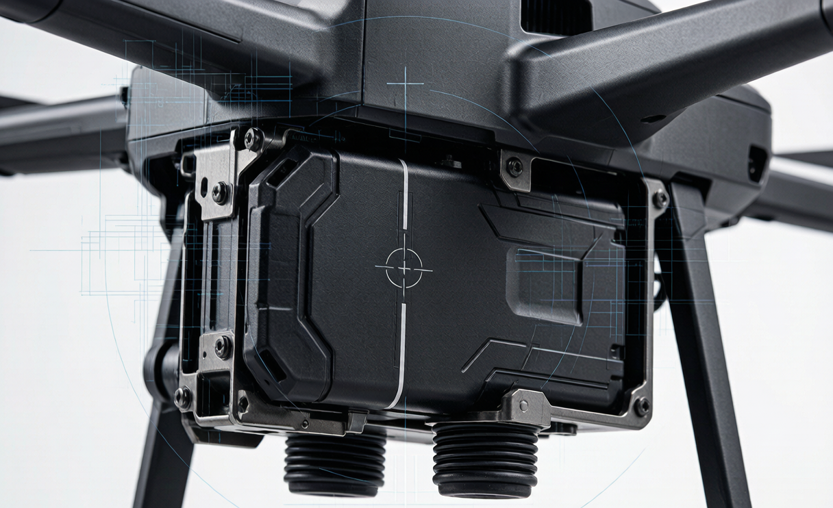
Over the last nine years I have designed drone lithium battery packs for survey, mapping, and inspection platforms, and the inspection segment is the one where mechanical co-design matters most. A typical inspection airframe carries a stabilized gimbal — LiDAR, a cooled thermal camera, or a multispectral payload — weighing anywhere from 0.5 kg to 2.5 kg, mounted low and forward. That mass dominates the airframe’s center of gravity (CG). If the battery is treated as an afterthought, the aircraft flies tail-heavy, the flight controller burns extra power to hold attitude, and the gimbal picks up airframe shake that ruins the data. Good drone battery design for inspection UAVs means engineering the pack as ballast, structure, and a vibration source you actively tame.
The Ballast Problem: Computing Center of Gravity From Pack Placement
The first decision is not chemistry — it is location. On a six-rotor inspection airframe I worked on in 2023, the gimbal and its damping cage came in at 1.8 kg, mounted 120 mm forward of the main spar. The airframe wanted a CG within ±15 mm of the spar for stable hover. The raw airframe minus battery came out 38 mm nose-heavy. The solution was to place a 1.4 kg lithium battery pack 95 mm behind the spar, shifting the combined CG back to +6 mm — inside tolerance without adding dead ballast.
The math is straightforward lever-arm balance: each mass times its distance from the reference sums to a weighted average. What surprises newcomers is how little room you have. A 6 mm CG error on that airframe translated to roughly 4% extra tail-rotor or rear-motor thrust just to hold level flight, which we measured as a 3–5% endurance penalty across a 22-minute mission. For an inspection operator flying 40 sorties a day, that is real money in flight time and battery cycle wear. This is why I treat the pack’s mounting position as a design variable, not a fixed constraint handed over by the airframe team.
Form-Factor and Mounting Co-Design
Once the CG target is set, the pack envelope is driven by dead volume, not by a catalog form factor. On inspection airframes there is usually an underbelly cavity between the landing skids that is wasted space in a standard build. We designed a flat, wide pack — 180 × 120 × 55 mm, 6S3P using 21700 cells — that filled that cavity exactly, lowering the pack’s centroid by 22 mm versus a top-mounted brick and improving pendulum stability in wind.
Quick-swap is non-negotiable for inspection fleets. We used a dual-rail guided dock with a single rotating latch, so a field technician swaps a pack in under 30 seconds without tools. The connector is a locking 8-pin with pin-assigned power and a Kelvin sense pair for the BMS, keyed so it cannot be inserted reversed. Harness routing runs along the frame spine in a shielded loom; I keep the high-current path and the battery-telemetry path physically separated by at least 15 mm to avoid the power-quality problems I have written about in our power-distribution work. The point of a good custom battery solution here is not a clever cell — it is a pack that disappears into the airframe and comes out fast.
Vibration Isolation: Keeping the Pack From Shaking the Sensors
A drone lithium battery pack looks inert, but it is a vibration source. Cells swell and relax slightly under load, the holding clamps transmit motor and propeller harmonics through the frame, and an out-of-balance pack acts like a small unbalanced rotor. Inspection payloads are brutally sensitive: a cooled thermal camera can resolve temperature differences below 50 mK, and a LiDAR APD receiver is blind to returns buried in airframe shake. At a 220 Hz propeller passing frequency we measured 0.6 g of frame vibration transmitted straight to a hard-mounted pack; that same 0.6 g reached the gimbal and showed up as image jitter.
The fix is two-stage elastomer isolation. We seated the pack on four silicone dampers rated at 18–22 Shore A, tuned so the isolated natural frequency sat around 12–15 Hz — well below the dominant 180–260 Hz motor harmonics, giving a transmissibility under 0.3 at the frequencies that matter. A secondary soft gasket between the pack lid and the dock killed the higher-order buzz. After isolation we re-measured gimbal-adjacent vibration at 0.08 g, and the thermal operator reported visibly cleaner imagery on long loiter passes. I validate every pack to an ISO 1940 balance grade and a MIL-STD-810H random-vibration profile (5–500 Hz, 1.2 grms qualified, 1.8 grms screened) before it ships.
CG-Stable Swapping and Multi-Payload Reconfiguration
One inspection airframe often flies several payloads in a week: a 0.9 kg optical zoom one day, a 2.1 kg LiDAR the next. The CG moves, and a fixed battery position cannot serve both. Our answer is a sliding pack tray with three indexed positions, each laser-etched with its compatible payload class. Moving the 1.4 kg pack between the forward and aft index shifts the combined CG by 34 mm — enough to re-trim the airframe for either payload without adding ballast.
Before every flight the operator runs a pre-flight CG gate: the BMS reports pack mass from its serialized build record, the ground software computes the expected CG from the selected payload profile, and it refuses takeoff if the result is outside ±15 mm. This sounds conservative until you remember that an inspection mission often ends in a precise hover-and-settle maneuver near a structure; a CG surprise there is how you clip a blade. A custom battery solution that knows its own mass and talks to the flight planner is worth more than ten Wh of extra capacity in the field.
Structural Integration and Crash Survival
The pack is also a structural member. In a hard landing or a rotor strike, the airframe loads the battery bay, and a poorly retained pack becomes a loose 1.4 kg projectile that can puncture cells. We designed the pack housing to carry the landing-load path: the cell block sits in a bonded aluminum tray with a crush zone at the leading edge, and the lid bolts share the frame’s skin load. In a 20 g drop test (well beyond the UN 38.3 T.1 1.2 m free-fall precondition we also certify against), the tray held, cell retention stayed intact, and no terminal shorted.
On the compliance side, every inspection pack we ship passes the full UN 38.3 T.1–T.8 sequence — altitude simulation, thermal test, vibration, shock, external short, impact, overcharge, and forced discharge — plus IEC 62133-2 cell-level safety, and IATA Section II air transport when the pack is under 100 Wh. For the larger 6S inspection packs that land around 88–96 Wh we keep them inside the Section II exemption; anything above 100 Wh is crated as Class 9 and shipped under the full dangerous-goods regime. Sealing is to IEC 60529 IP67 so a sudden rain squall or a turbine misting does not reach the cells. A lithium battery that survives the environment is more valuable to an inspection operator than one that merely survives the datasheet.
Frequently Asked Questions
Can the same drone battery pack serve both light and heavy inspection payloads?
Yes, if the pack is mounted on an adjustable tray. We use three indexed positions that shift the combined center of gravity by up to 34 mm, letting one 1.4 kg pack trim the airframe correctly for payloads from 0.9 kg to 2.1 kg. A pre-flight software gate then confirms the CG is within tolerance before takeoff.
Why does vibration isolation matter more on inspection drones than racing drones?
Racing drones care about power and mass; inspection drones care about data quality. A cooled thermal camera or LiDAR sees airframe shake as image jitter or lost returns. We measured 0.6 g of frame vibration reaching a hard-mounted pack and reduced it to 0.08 g with two-stage elastomer isolation, which directly improved inspection imagery.
How do you keep the battery from becoming dead weight when used as ballast?
By placing it where its mass solves a CG problem instead of adding ballast. On one six-rotor airframe the 1.4 kg pack was positioned 95 mm behind the spar specifically to counter a nose-heavy gimbal, moving the combined CG into tolerance without any added dead mass.
What certifications apply to an inspection UAV battery pack?
The baseline is UN 38.3 T.1–T.8 for transport safety, IEC 62133-2 for cell safety, IATA Section II for air shipping below 100 Wh, and IEC 60529 IP67 for environmental sealing. We also qualify to a MIL-STD-810H random-vibration profile and an ISO 1940 balance grade for the mechanical co-design work.
Does using the pack as a structural member risk damaging the cells?
Only if it is done carelessly. We bond the cell block into an aluminum tray with a leading crush zone and let the lid bolts share skin load, so the pack carries landing loads safely. In a 20 g drop test the tray held, cells stayed retained, and no terminal shorted — exceeding the UN 38.3 1.2 m free-fall precondition.





