
Drone Battery Design for Inspection UAVs: Engineering th (2)
As a senior lithium battery engineer at Horizon Power, I have spent the better part of a decade designing drone battery packs for industrial inspection work — rooftop PV arrays, telecom towers, pipeline corridors, and confined-space tank audits. If you have ever watched an inspection quadcopter hold a stationary hover for twenty minutes with a gimbal, a LiDAR pod, and a thermal camera hanging beneath it, you already know the hardest constraint on these missions is rarely energy. It is heat. A mapping or racing drone is almost always moving; an inspection drone hovers. Hovering is the cruelest duty cycle for a lithium battery because the rotors pull maximum current at near-zero airspeed, the prop wash that might cool the pack is feeble, and the payload bay wraps the cells in something close to a thermal blanket.
This is the tenth piece I have written on drone battery design for inspection UAVs, and I want to spend it on the factor that quietly decides whether a pack thrives or fails in the field: the thermal envelope. By that I mean the band of temperatures the pack must stay inside — from a -10 °C pre-dawn startup on a water tower to a 48 °C afternoon on a black membrane roof — and the deliberate engineering we do to keep every cell inside that band. I will walk through heat-path design, CFD-informed cell layout, and the part most procurement checklists skip but every risk manager asks about: thermal-runaway containment.
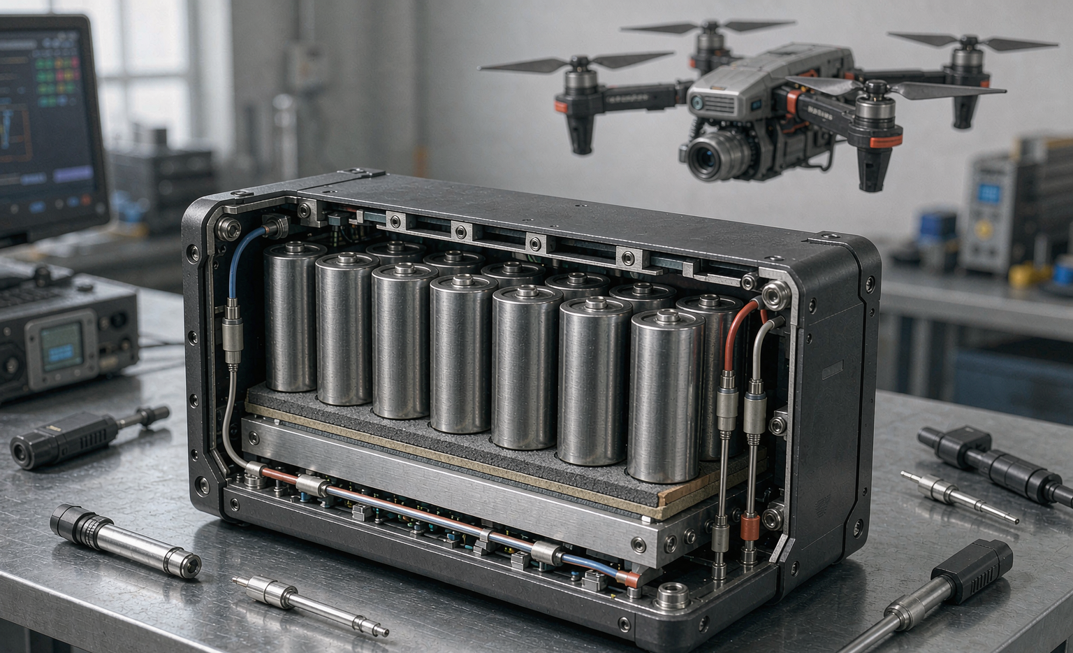
Why an inspection drone battery fights heat differently
Most people picture a drone battery as a “fuel tank.” For inspection work that mental model breaks. The defining feature of inspection flight is sustained hover at high discharge with little cooling airflow. A typical 6S 21700 inspection pack delivering 30–40 A continuous pushes cell temperatures up by 8–15 °C above ambient within the first ten minutes of hover, and the climb is non-linear: as internal resistance rises with temperature, I²R heating accelerates. Add a 40 °C rooftop in midsummer and the cell cores can approach 60 °C — the point where most lithium chemistries begin to shed cycle life rapidly and where separator margins thin.
Contrast that with a mapping drone transiting at 12 m/s; its forward flight drives 5–15 km/h of relative airflow across the pack, often cutting cell temperatures by 10–20 °C versus hover for the same power draw. Inspection simply cannot rely on motion for cooling. The pack itself has to be the heat sink, the duct, and the firewall. That is why drone lithium battery design for inspection is first and foremost a thermal design problem, not an energy-density one.
Defining the thermal envelope — the band we design inside
Before I draw a single cell, I write down the thermal envelope as a hard contract. For the inspection packs we ship, the operating band is -10 °C to +50 °C ambient, with a maximum sustained cell-surface temperature of 60 °C and a core limit of 55 °C. Inside that band, end-of-life capacity fade must stay within spec and no cell may approach the onset of thermal runaway.
The three heat loads that fill the envelope
There are three distinct contributions. First, I²R ohmic heating in cells, welds, busbars, and the sensing harness — this scales with the square of current, so a 40 A hover can dissipate three to four times the heat of a 20 A cruise. Second, entropic (reaction) heat inside the cell, which is chemistry-dependent and non-linear near full charge. Third, the incident loads the environment piles on: solar gain on a dark roof (easily +5 to +10 °C on an exposed pack), and the heat leaking inward from a nearby payload like a spotlight or a high-power LiDAR. A good custom battery solution budgets for all three, not just the electrical term.
Heat-path engineering — getting heat out before it builds
The first lever is the conduction path. A bare cylindrical cell in still air rejects heat almost entirely through its own surface, and a 21700 at 1.5–2.0 A is already temperature-limited by that surface area. We bond cells to an aluminum heat-spreader plate (roughly 230 W/m·K) with a thermal interface material rated 1.5–3.0 W/m·K, which drops the cell-to-plate resistance from about 1.5 K/W to under 0.4 K/W. That single change can shave 6–10 °C off peak cell temperature in a long hover.
The second lever is layout for convection. We leave 2–4 mm of vent gaps between parallel cell rows and orient them so the weak prop wash and natural buoyancy form a continuous chimney. In CFD we look for dead zones — pockets where air stalls — because those are where a cell quietly overheats while its neighbor runs cool. Third, we size the structure for mass without punishing the thrust-to-weight budget: a heavier pack flies shorter, so the spreader plate is often a thin extruded 5052 alloy ribbed only where the thermal gradient demands it.
CFD-informed cell layout and spacing
I refuse to lay out an inspection pack by eye. We run a steady-state conjugate-heat-transfer model at the worst-case hover current and the worst-case ambient, then iterate. The model tells us three things: the peak-cell location (almost always the center cell in a 3P group, the one with the least exposure), the magnitude of the center-to-edge gradient (we target under 5 °C), and whether the chimney works. When the gradient is too high we either widen spacing, add a perimeter vent slot, or move the hottest 2P group to the pack edge. For a 6S3P 21700 design this typically means an 18–22 mm total pack height with two internal vent planes rather than one solid block.
Thermal-runaway containment — one cell fails, the pack must not
Hover missions often fly over people, assets, and ignition-sensitive sites, so a single-cell fault must never become a pack fire. This is the part of drone battery design inspection teams should interrogate hardest.
Barrier materials and propagation resistance
We separate adjacent cells and cell groups with a barrier stack — typically 0.3–0.5 mm mica or aerogel-backed foil plus a 1–2 mm inorganic spacer — chosen so that a cell at 600–800 °C does not push its neighbor past the onset of exotherm. The design target we verify against is no propagation to the adjacent cell within the standard observation window. This is not decoration; it is the difference between a pack that vents safely and a pack that takes the airframe with it.
Vent paths and pressure relief
An abused cell vents hot gas and ejecta. We give that gas a path: directional vent slots in the enclosure, a standoff from the flight controller and payload, and a melt-blown flame-arrestor screen at the relief port. The goal is to relieve pressure and cool ejecta below ignition without letting the vent plume cook the propulsion wiring. In our enclosures the relief path is sized for the gas volume of the largest plausible single-cell event, with margin for two near-simultaneous vents.
The BMS thermal layer — sensing, derate, isolation
Hardware containment is the backstop; the BMS is the prevention layer. Every inspection pack we build carries per-cell NTC thermistors (one per parallel group, sometimes two for the center cell), sampled at 1–10 Hz. The firmware runs a two-stage thermal derate: above 45 °C it trims available discharge current by a calibrated curve, and above 50 °C it hard-limits to a safe crawl that still lets the pilot land. We also watch the rate of rise, not just the absolute value — a cell climbing 2 °C/s while its neighbors sit flat is an early-warning signature of an internal fault, and the BMS flags it long before temperature alone would.
A worked thermal budget — a 6S3P 21700 inspection pack
Take a representative 22.2 V, 3.0 Ah pack (six groups of three 21700 cells) on a tower inspection: 38 A continuous hover, 60 A 10 s burst, 35 °C ambient. With no spreader, our model predicts a center-cell surface of 68 °C — over limit. Add the aluminum spreader plus TIM and the vent chimney and the same mission lands at 57 °C surface / 52 °C core, inside envelope with roughly 3 °C margin. The derate curve never trips because we sized the cells for 45 A continuous, not the 38 A nominal. That margin is the whole point: this drone lithium battery should run cool enough that the BMS never has to save the mission.
From drawing to evidence — standards that close the loop
Thermal claims mean nothing without test evidence. Our inspection drone battery lines are qualified against UN38.3 (T.1–T.8, including the T.6 altitude/thermal-abuse and impact tests), IEC 62133-2 for cell and pack safety, and UL 2580 / IEC 62619 for the thermal-propagation and abuse resistance that containment design must demonstrate. For air transport we stay inside the FAA Part 107 and EASA 100 Wh per-battery limits and ship under IATA Section II. A custom battery solution for a specific inspection airframe usually adds a customer-specific thermal validation — a chamber soak at the rated ambient followed by a back-to-back hover mission while we log every cell.
Frequently asked questions
How hot is too hot for an inspection drone battery?
For the packs we ship, the line is a 60 °C sustained cell-surface temperature and a 55 °C core. Above that, fade accelerates and separator margins shrink. The BMS begins derating at 45 °C and hard-limits by 50 °C, so a healthy pack should never let you reach the hard limit during normal inspection.
Can passive cooling really handle long hover inspections?
In most inspection missions up to roughly 30–40 minutes of hover at moderate current, yes — a spreader plate, TIM, and a CFD-tuned vent chimney are enough. For very high-current or hot-climate missions we either enlarge the conduction path or step up to a slightly larger cell count to lower the per-cell load. Active cooling is rarely worth the mass and failure surface on a small UAV.
Which standard proves thermal runaway won’t propagate?
No single universal certificate “proves” zero propagation, but UL 2580 and IEC 62619 are the recognized benchmarks for thermal-propagation resistance in stationary and mobility packs, and UN38.3 T.6 covers thermal abuse. We use all three plus our own single-cell-to-adjacent propagation test as the acceptance gate.
Why does ambient temperature matter more for inspection than for mapping?
Because inspection hovers. A mapping drone’s forward flight creates cooling airflow that mapping packs exploit; an inspection drone sits in still, often hot, air. The same 35 °C afternoon that barely dents a mapping mission can push a hovering pack to its thermal ceiling. That is why inspection thermal design starts from worst-case ambient, not average.
How do you verify thermal design before the first flight?
CFD first, then a chamber soak at rated ambient, then a back-to-back hover on a test stand with per-cell temperature logging, then the abuse and propagation tests above. Only after the model, the stand, and the standards all agree do we release the pack for field inspection.





