
Drone Battery Manufacturing for Mapping UAVs
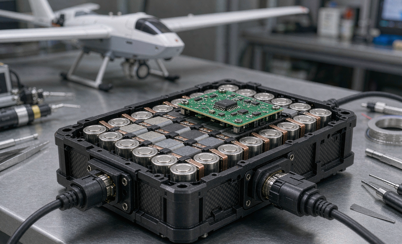
When a survey team launches a fixed-wing mapping UAV at dawn to photogrammetry a 40 km pipeline corridor, the success of that mission was decided long before takeoff — it was decided on the factory floor. Over fifteen years of building drone battery packs for mapping, surveying, and inspection fleets, I have learned that a reliable mapping pack is not born in the CAD file. It is born in the incoming cell grading, the laser weld, the formation cycle, and the burn-in rack. Design sets the ceiling; manufacturing sets the floor. And for mapping UAVs, where fleets fly dozens of airframes against tight endurance and data-quality budgets, the floor matters more than almost any single headline specification.
This article walks through how we manufacture a mapping-grade drone lithium battery — the process discipline that turns raw 21700 cells into fleet-ready packs with the consistency mapping operations actually depend on. If you are specifying a custom battery solution for a mapping program, the questions below are the ones that separate a pack that survives one good flight from one that survives a thousand.
Why the Factory Floor, Not Just the Drawing Board, Decides Mapping Missions
A mapping UAV flies a predictable but unforgiving duty cycle: long, steady partial-throttle cruise; repeated climb-and-level transitions; and a sensor payload — typically a gimballed RGB camera, a LiDAR head, or a multispectral array — that demands a clean, stable bus. The pack does not see the violent punch-outs of a racing quad. It sees hours of moderate draw with almost no recovery time between flights, because mapping fleets turn around fast. That profile exposes manufacturing variation more than design variation.
Two packs can share an identical schematic and still deliver wildly different fleet behavior if one leaves the line with cell-to-cell DCIR spread of 8% and the other at 2%. The 8% pack will age unevenly, hit its voltage cutoff first, and force the operator to land while the other keeps flying. Across a 20-aircraft fleet, that single manufacturing variable quietly rewrites your endurance model. So when we talk about manufacturing a mapping drone battery, we are really talking about distribution control, not just nominal performance.
Incoming Cell Qualification — Grading Before a Single Weld
Manufacturing begins before assembly. Every 21700 cell that enters our line is individually qualified against four gates, and only cells that pass all four are admitted to a matched group:
- Capacity grading at 0.2C constant current to 2.5 V cutoff, binned to ±1% of nominal. Mapping packs are built only from a single capacity bin.
- DCIR screening via a 10-second 10 A pulse with four-wire Kelvin sensing. We reject any cell whose DCIR deviates more than 6% from the bin median.
- Self-discharge (K-value) measured as open-circuit voltage drift over a 72-hour rest at 25 °C. We require K < 1.0 mV/day; anything above 2.0 mV/day is a latent internal-defect escape and is quarantined.
- AC impedance and OCV sanity checks to catch separator defects invisible to a capacity test alone.
The point of this incoming discipline is matching, not selection. A mapping lithium battery pack built from tightly matched cells balances passively, stays cool, and ages uniformly — which is exactly what a multi-hour cruise needs. We record the lot, grade, and individual serial of every cell, because that data becomes the seed of the pack’s genealogy.
Laser Welding and Interconnect Manufacturing at Cpk-Controlled Tolerances
The single most failure-prone joint in any cylindrical-cell pack is the nickel or nickel-plated busbar weld. A cold weld raises resistance; an overheated weld anneals the tab and weakens it; a porous weld fractures under the gentle but relentless vibration of a mapping airframe. We run pulsed fiber-laser welding with a process-capability target of Cpk ≥ 1.67 on weld nugget resistance, meaning fewer than roughly 0.6 ppm of joints fall outside tolerance.
Every weld is verified, not assumed. We use a combination of:
- X-ray inspection on a statistical sample (and 100% on first-article and engineering-change runs) to confirm nugget penetration and absence of porosity.
- AI-assisted optical inspection for splash, discoloration, and tab alignment.
- 4-wire resistance verification of the finished busbar string, which must read below 0.15 mΩ per joint and show less than 15% spread across the pack.
A mapping drone battery that loses a single series weld mid-flight does not just lose capacity — it loses the entire string. Cpk-controlled welding is the reason our field warranty rate on interconnect failures sits below 0.2% per 1,000 flight-hours.
Formation and Capacity Grading — the First True Charge
Once assembled, a pack has never been fully charged. The formation step is its first real electrochemical life: a controlled constant-current/constant-voltage first charge that stabilizes the solid-electrolyte interphase (SEI) layer on the anode. This is not a test; it is part of the manufacturing process that defines the pack’s long-term behavior.
We formation-charge at a conservative 0.1–0.2C with a tightly regulated cutoff, then perform a full capacity grading cycle. The result is twofold:
- The SEI stabilizes under controlled conditions rather than on the customer’s first charge, where a fast charger could induce lithium plating.
- We capture the pack’s true delivered capacity and bin it, so a fleet order ships with packs matched to within 1.5% of each other.
For mapping operators, matched pack-to-pack capacity is what makes “swap any pack into any airframe” logistics possible. Without it, you are balancing flights around individual pack quirks — a hidden operational tax.
Multi-Stage Aging and Burn-In — Screening the Fleet Before the Fleet Flies
Formation is followed by the step most often skipped by low-cost assemblers: aging and burn-in. A fresh pack’s weakest elements — a marginally welded joint, a borderline cell, a loose sense wire — rarely fail in the first cycle. They fail in the third or the thirtieth. Burn-in is how we let them fail on our bench instead of over a client’s pipeline.
Our mapping-pack burn-in sequence runs three stages:
- Thermal cycling: the pack is held at −10 °C, 25 °C, and 50 °C while under a representative mapping duty profile, surfacing temperature-sensitive resistance shifts.
- Rest and recovery: a 48-hour room-temperature rest to expose self-discharge and micro-leakage that only appear after the SEI settles.
- Re-test gate: every pack is re-measured for capacity (must retain ≥98% of formation value), DCIR (must not drift more than +10%), and balance (cell spread ≤30 mV). Anything outside the gate is torn down, root-caused, and either rebuilt or scrapped.
This is where a manufactured drone lithium battery earns the right to be called flight-grade. The burn-in rack is the cheapest insurance a mapping program can buy, because a pack that fails in week two of a survey contract costs far more than the bench time to catch it.
MES Traceability and the DataMatrix Genealogy of Every Pack
None of the above is useful if it cannot be recalled. Every mapping pack we build carries a laser-etched DataMatrix code that links to a Manufacturing Execution System (MES) record containing:
- The lot, grade, and serial of every cell and its incoming K-value and DCIR.
- The weld recipe and X-ray/optical inspection result for each joint.
- The formation and burn-in curves, with pass/fail against every gate.
- The technician, line, and timestamp of each operation.
When a fleet reports an anomaly, we do not guess — we pull the genealogy, compare it against sibling packs from the same lot, and isolate whether the cause is a cell lot, a weld parameter drift, or a field abuse pattern. For a custom battery solution deployed across a multi-year mapping program, this closed loop is what keeps a fleet flying as it scales from 10 to 200 airframes.
The Mapping-Specific Discipline — Pack-to-Pack Consistency as a Spec
Here is the discipline I urge every mapping program manager to write into their procurement specification: treat pack-to-pack consistency as a numbered requirement, not a hope. Concretely, we hold:
- Capacity spread across a shipped fleet lot: ≤1.5%.
- DCIR spread within and across packs: ≤6% from the lot median.
- Full-charge voltage at end of CC phase: matched to ±20 mV pack-to-pack.
- Self-discharge after burn-in: K < 1.0 mV/day, verified per pack.
Why does this matter more for mapping than for, say, cinematic flight? Because mapping is a fleet and data problem. Inconsistent packs produce inconsistent flight times, which produce inconsistent coverage per sortie, which produces gaps in the orthomosaic that somebody has to fly again. A drone battery manufacturing process built around distribution control is, in the end, a data-quality investment.
Standards still frame the floor. Every pack we ship complies with UN38.3 (T.1–T.8 transportation testing), IEC 62133-2 (secondary cell safety), and the relevant air-transport limits of 100 Wh per pack under FAA and EASA rules, with IATA Section II documentation for multi-pack shipments. But as I tell every client: certification tells you a pack is legal to fly. Manufacturing discipline tells you it will still be legal — and reliable — on flight 800.
Frequently Asked Questions
Does incoming cell grading really change field reliability for mapping drones?
Yes, measurably. Tightly graded cells (DCIR CoV under 6%, capacity within ±1%) balance passively and age together, which extends usable cycle life and keeps pack-to-pack flight times consistent — the single biggest operational lever for a mapping fleet.
Why is burn-in worth the extra lead time?
Burn-in surfaces weak joints, borderline cells, and loose sense wires that only fail after several cycles. Catching them on the bench costs a few days of lead time; catching them over a client’s survey corridor can cost a contract. For a flight-critical lithium battery, it is the cheapest insurance available.
What weld quality should I require from a battery supplier?
Ask for Cpk ≥ 1.67 on weld nugget resistance, X-ray or AI optical verification, and a documented per-joint resistance target below 0.15 mΩ with under 15% pack-wide spread. Interconnect failure is the most common catastrophic field mode on a mapping drone battery.
How does traceability help after delivery?
A DataMatrix-linked MES genealogy lets us root-cause any field anomaly against the exact cell lots, weld recipes, and burn-in curves of the affected pack, then compare across siblings. That turns a vague failure report into a precise, repeatable fix within a custom battery solution.
What consistency numbers should I put in a procurement spec?
Require fleet capacity spread ≤1.5%, DCIR within 6% of lot median, end-of-CC voltage matched to ±20 mV pack-to-pack, and post-burn-in self-discharge K < 1.0 mV/day. These four numbers predict mapping fleet behavior better than any marketing C-rating.





