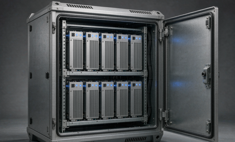
Lithium Battery Integration for UPS Systems

After twenty-plus years specifying lithium battery systems for industrial customers, I have learned that the word “integration” hides most of the risk on a UPS project. Buying a good lithium battery pack is the easy part. The hard part is persuading a machine that was designed around the electrical personality of a flooded or VRLA lead-acid string to behave correctly with a chemistry whose internal resistance is roughly five to ten times lower, whose charge acceptance is five to ten times higher, and whose protection threshold is not a voltage but a decision made by a microcontroller.
This article is not about chemistry selection — I covered the measurement side in my piece on lithium battery performance for UPS systems, and the design side in my article on lithium battery design. This one is about the interface: the DC bus, the charger, the protection, the communications, the concrete, and the moment you first transfer the load. Everything below comes from retrofits and greenfield installs I have personally signed off, including several that did not go well the first time.
What “Integration” Actually Means on a UPS
Installation is bolting a cabinet to the floor and landing cables. Integration is making four separate decisions agree with each other:
- Voltage decisions. What the UPS considers “full,” what it considers “empty,” and what it does at each end.
- Current decisions. How much charge current the rectifier offers, how much the battery accepts, and what happens when those two numbers disagree by an order of magnitude.
- Protection decisions. What clears a fault, in what order, and how fast — with a source that can deliver far more current than the one the switchgear was selected for.
- Sequence decisions. Who shuts down the load first: the UPS, on a warning, or the battery management system, by opening a contactor. If the answer is the battery, the integration has failed.
Every serious field failure I have investigated on a lithium UPS retrofit traces back to one of those four. None of them are chemistry problems.
The Retrofit Case Is Where the Trouble Lives
A greenfield installation with a matched UPS and battery from one supplier is comparatively easy: someone else already reconciled those four decisions. The retrofit case — a ten- or fifteen-year-old 200 to 800 kVA UPS with a dead VRLA string — is where I spend most of my time, and it is where the rest of this article lives.
The Voltage Window Mismatch: The Single Most Common Integration Failure
A legacy 480 V VRLA string is 240 cells of 2 V. Every UPS on the market has that string’s numbers baked into its firmware:
- Float: 2.25 to 2.27 V per cell, i.e. 540 to 545 V
- Equalize or boost: 2.35 to 2.40 V per cell, i.e. 564 to 576 V
- End of discharge (EOD): 1.67 to 1.75 V per cell, i.e. 400 to 420 V
Now take a lithium string of 160 cells in series — ten 51.2 V LFP modules — which is 512 V nominal:
- Full charge at 3.45 to 3.50 V per cell: 552 to 560 V
- Practical end of discharge at 2.8 V per cell: 448 V
- Absolute cell low-voltage cut: typically 2.5 V per cell, i.e. 400 V
Look at where those two windows sit relative to each other. The lithium pack’s full-charge voltage (552 to 560 V) sits above the VRLA float voltage (540 to 545 V) but below the VRLA equalize voltage (564 to 576 V). This produces two failure modes that I see constantly, and they are mirror images of each other.
Failure Mode One: The Pack That Never Charges
Leave the UPS on its VRLA float setting and the lithium string sits at 540 to 545 V — which is about 3.38 to 3.41 V per cell. That is a partial state of charge, typically somewhere in the 60 to 80 percent band depending on temperature and the cell’s OCV slope. The BMS never sees the voltage threshold at which it starts passive balancing in earnest, cell divergence accumulates, and the pack’s usable capacity quietly shrinks over weeks.
The symptom that reaches the customer is not “the battery is undercharged.” It is “runtime is shorter than the proposal promised,” reported three months after commissioning, by which point everyone has assumed the battery is defective and stopped looking at the charger setting. I now make “verify the UPS float voltage against the pack’s specified charge voltage” item one on every commissioning sheet, and I record the actual measured string voltage with the load on the rectifier for at least thirty minutes.
Failure Mode Two: The Unattended Overvoltage Trip
Many VRLA UPS run a periodic equalize or boost charge — monthly, quarterly, or after any discharge. If that cycle is still enabled, the bus goes to 564 to 576 V, which on a 160-cell lithium string is 3.53 to 3.60 V per cell. That is past the cell overvoltage protection on essentially every LFP pack I have worked with.
The BMS opens its contactor. The UPS, which believes the battery simply vanished, may drop the load on a battery-backed transfer that was never supposed to happen. And because equalize cycles run on a timer, they reliably fire at 2 a.m. on a Sunday with nobody in the building.
The fix is not to disable the boost function blindly. It is to reprogram the rectifier with the lithium profile the battery manufacturer specifies — charge voltage, current limit, and no temperature-compensated float, because LFP’s temperature coefficient is not lead-acid’s and a temperature-compensated float on lithium pushes the voltage the wrong direction at exactly the wrong time.
Failure Mode Three: The EOD That Arrives After The Contactor Opens
On discharge, the UPS is waiting for 400 to 420 V before it declares “battery low” and shuts down gracefully. On a 160-cell lithium string, 400 V is 2.5 V per cell — below the LFP knee, and at or below the BMS undervoltage cut. So the contactor opens at roughly the same moment as, or slightly before, the UPS’s graceful-shutdown threshold.
The practical rule I use: the UPS must reach its low-battery alarm at least two minutes before the BMS can open its contactor, and the site’s actual graceful-shutdown sequence must fit inside that gap with margin. Two minutes is my floor for small sites; on a facility that has to shut down a chilled-water plant or a database cluster gracefully, I have specified ten. The number is not arbitrary — it is the measured shutdown time plus 50 percent.
Then test it by forcing the alarm rather than by waiting for it. I have never once seen a site discover an integration gap by reading the settings on a screen; they discover it during a real outage, which is the most expensive possible test lab.
Sizing for the End of Discharge, Not the Nominal Voltage
This is a sizing error that survives design review more often than it should. A UPS is rated in kVA; the battery must deliver real kilowatts through an inverter whose input current rises as the DC bus sags.
Take a 200 kW load. At a nominal 512 V with an inverter efficiency of 0.95, the battery current is about 411 A. Now run the same load at the end-of-discharge bus voltage of 448 V:
- I = 200,000 ÷ (448 × 0.95) = 470 A
That is roughly 14 percent more current at the moment the system has the least margin left. I generally design for 20 percent headroom over nominal to cover a colder-than-expected room (which raises internal resistance and drops voltage further) and an inverter efficiency curve that is worse than the datasheet at part load.
The consequence for integration is concrete: cable cross-section, DC breaker rating, and the BMS continuous current limit must all be set from the end-of-discharge current, not the nominal one. I have reviewed retrofit drawings where the cable was sized at nominal and the BMS overcurrent protection then tripped at 88 percent depth of discharge — the pack was fine, the integration was wrong, and the customer’s conclusion was that lithium cannot do the job.
Ripple Current: Where Low Internal Resistance Stops Being Free
Low internal resistance is why lithium wins on runtime and on recharge. It is also a liability on a UPS DC bus, and almost nobody checks it.
A phase-controlled or even a modern IGBT rectifier leaves an AC component on the DC link. For a given ripple voltage, the ripple current into the battery is set by the battery’s impedance at the ripple frequency — 300 or 360 Hz for a six-pulse rectifier, 600 or 720 Hz for twelve-pulse. Swap a VRLA string with tens of milliohms for an LFP string with a few milliohms and the ripple current rises by the same ratio. The pack’s heating from ripple is real, and at high state of charge, sustained ripple current is not something I want on any lithium cell.
Two practical points:
- Get the number in writing. Many lithium datasheets publish a maximum ripple current; many do not. Where there is no published figure, I hold to 0.1C rms or 5 A rms, whichever is lower, and I say so in the specification before anyone bids.
- Measure it at light load, not just full load. Ripple as a fraction of DC current is often worst when the UPS is lightly loaded, which is the normal condition for a redundant system. Measure with a true-RMS clamp plus a DC- capable current probe, or a shunt and a scope with the bandwidth to see 720 Hz.
Ripple also confuses coulomb counting. If the BMS reports a state of charge that jitters or drifts, suspect the measurement environment before you suspect the cells.
Pre-Charge and Inrush: The Contactor-Welding Problem
A 200 kVA UPS has a DC link with thousands of microfarads behind it. When that link is at zero and a 550 V lithium string is connected through a contactor, the only things limiting current are the loop resistance and inductance — which, in a pack this stiff, means a peak in the kiloamp range for a few hundred microseconds.
That is enough to weld contactor faces, and it happens on the very first close, or worse, on the hundredth close when nobody is watching. In one retrofit I was called to investigate, the symptom was a battery cabinet that would not disconnect on command — the main contactor had welded shut, and the BMS had been reporting “closed” because it was commanding open and reading an auxiliary contact that had welded too.
The correct architecture is a pre-charge path: a resistor in series with a small contactor or an electronic pre-charge circuit, which brings the DC link up over three to five time constants, then a main contactor that closes across the resistor once the differential voltage is small. With a 10,000 µF link and a 50 Ω pre-charge resistor, tau is 0.5 s and the sequence takes about 2.5 s. That is a normal, expected delay — and I have seen commissioning engineers diagnose it as a fault.
Three integration rules follow:
- Never reuse an existing battery breaker as the sole closing device for a lithium string unless you have confirmed a pre-charge path exists upstream.
- Verify the pre-charge works with a current probe on the first close. Measure the peak, not the average.
- Never hot-plug a module into a live string. The module’s own capacitors charge through its connector pins, and the pins are not rated for it.
Protection Coordination: The Fault Current Went Up and Nobody Told the Breaker
This is the item most likely to be missed entirely on a retrofit, and it is the one with the worst consequence.
A 480 V VRLA string has substantial internal resistance — commonly 50 to 150 mΩ for the whole string. A 512 V LFP string of the same amp-hour rating might be 10 to 20 mΩ. Apply Ohm’s law at 500 V:
- VRLA at 100 mΩ: about 5 kA prospective short-circuit current
- LFP at 15 mΩ: about 33 kA prospective short-circuit current
The existing DC disconnect, selected a decade ago for a lead-acid string, may have a 10 kA interrupting rating. It will not clear a 33 kA fault. It may not survive attempting it.
What I require on every lithium UPS integration:
- A calculated prospective short-circuit current at the battery terminals, using the actual pack resistance and the actual cable impedance, not a rule of thumb.
- DC-rated overcurrent protection with an interrupting rating above that value. IEC 60947-2 gives DC ratings for moulded-case breakers, usually requiring multiple poles in series; IEC 60269-4 covers semiconductor fuses (aR or gR class) where you need fast clearing and a defined I²t below what the cells can withstand.
- Selectivity verified on time-current curves between the battery protection, the UPS DC input protection, and any downstream distribution.
- Explicit acknowledgement that the BMS contactor is not a fault-clearing device. It is a load-break switch at best. If the design relies on the BMS to interrupt a short circuit, the design is wrong.
- A DC arc-flash assessment before any live work. The methods are not the same as for AC, and the incident energy on a stiff lithium bus is not something to estimate by feel.
The standard stack I reference: IEC 62485-2 for safety of stationary lithium installations, IEC 62619 for the battery itself, UL 1973 and UL 9540 for North America, IEC 62040-1 and IEC 62040-3 for the UPS, and UN 38.3 for anything that has to be shipped to site — the test summary has been a mandatory public document since 2020, and I ask for it before the pack leaves the factory, not after.
BMS-to-UPS Communication: Build an Alarm Ladder, Not a Trip Wire
The most common definition of “integrated” I encounter is: the UPS display shows the battery state of charge. That is a nice feature. It is not integration.
Real integration means every BMS condition that can end the discharge has a corresponding UPS action that happens earlier. I specify a four-level ladder:
- Level 1 — Inform. State of charge below 30 percent, or any single cell below 3.10 V: log it, raise it to the building management system, send the email. Nothing changes electrically.
- Level 2 — Derate. Cell temperature above 50 °C, or below 0 °C: stop charging. Most LFP packs will not accept charge below freezing anyway, but I want the UPS told, so that it does not sit there waiting for recharge that is never coming while a generator runs unnecessarily.
- Level 3 — Act. State of charge below 20 percent or minimum cell below 3.00 V: the UPS initiates the graceful shutdown sequence and, where a generator exists, starts it earlier than the lead-acid settings would.
- Level 4 — Last resort. Minimum cell below 2.50 V, or cell temperature above 60 °C: the BMS opens its contactor.
The design rule is that Level 4 must never be the event that removes power from the load. It is a firebreak, not a control action. If your shutdown sequence is triggered by Level 4, you have an ungraceful shutdown, and the only question is how expensive the day turns out to be.
On protocols: Modbus RTU over RS-485 is the workhorse, Modbus TCP and SNMP where there is a network management system, CAN on some integrated platforms. My non-negotiable is that at least two dry contacts get wired regardless of whatever data bus is installed: one general battery alarm, and one “disconnect imminent.” Voltage-free contacts fail safe, they do not depend on a baud rate being right, and they are what you test at 2 a.m. by shorting a terminal with a screwdriver.
Generators and Charge Acceptance
Lithium’s fast recharge is a genuine operational benefit and a genuine generator trap. A pack that will accept 1C can easily demand more than the genset’s continuous rating once you add the load back on top, and the result is frequency excursion and a genset that trips on its own protection.
I set the UPS charge current limit as a percentage of the generator’s continuous kW rating — typically holding total rectifier demand at 70 to 80 percent — and I delay recharge until the generator has been stable for a defined interval. On one hospital project, that single setting was the difference between a clean monthly test and a transfer failure that would have shown up during a real outage.
Never Mix Chemistries, and Be Careful With Parallel Strings
I still get asked whether the old VRLA string can stay connected as a “backup.” The answer is no, and the reasoning is not about safety slogans:
- The two chemistries need different charge voltages. Setting the bus to satisfy lithium undercharges the lead; setting it to satisfy lead overcharges the lithium.
- Their open-circuit voltage curves cross in the middle of the discharge, so load sharing during a transient is unpredictable and mostly borne by the low-impedance string — which then hits its protection first.
- They age at wildly different rates, so whatever balance you commission drifts within a year.
Parallel lithium strings are legitimate, but they are a design, not a default:
- Identical model, identical firmware, identical capacity — no exceptions.
- Brought to within a few percent state of charge before paralleling, or you will push circulating current that the BMS may read as a fault.
- Equal cable lengths to equalise impedance; I mean truly equal, not “roughly.”
- Written confirmation from the manufacturer that parallel operation is supported and a stated circulating-current limit.
- Protection re-checked, because paralleling halves the source impedance and roughly doubles the fault current.
Physical Integration: Weight, Floor, Seismic, and Temperature
The headline benefit of lithium on a UPS is density, and the numbers are real. For a mid-size 512 V string at around 100 Ah, a VRLA configuration lands in the region of 1,200 kg across multiple racks, while the comparable LFP system is typically 450 to 550 kg in a single cabinet — roughly a third of the weight and appreciably less floor area. The exact figures are model-specific and I insist on the actual datasheet weights, but the order of magnitude holds and it changes the building.
Three things follow that catch people out:
Raised Floors Are Rated for Point Loads
“It is lighter than the lead-acid bank” is not a structural argument if you are moving the battery from a dedicated battery room onto a raised floor next to the UPS. Typical raised-floor tiles are rated somewhere around 4.4 to 6.7 kN concentrated load, and a 500 kg cabinet on four feet puts about 1.2 kN through each — fine on the pedestals, not fine mid-tile. I require the cabinet corners to land on pedestals or on a load-spreading plinth, and on heavier systems I prefer a plinth that transfers load to the slab directly.
Seismic Anchorage Still Applies, and It Is Easier
A lighter cabinet develops lower seismic base shear, so anchorage is generally easier than the VRLA racks it replaces — but it still has to be calculated and detailed rather than improvised with whatever anchors are in the van. Under IBC and ASCE 7 in the United States, or EN 1998 in Europe, the deliverable is a stamped anchorage detail, and I want it in the submittal package rather than discovered at inspection.
Temperature Tolerance Is Resilience, Not an Operating Target
LFP cells are typically specified for charging between 0 and 45 °C and discharging over a much wider band. VRLA, by contrast, is designed around 20 to 25 °C and its life roughly halves for every 10 K above that.
That comparison is accurate, and it is where people reach the wrong conclusion. Yes, lithium removes the need for the hydrogen dilution ventilation calculation that EN 50272-2 drives for VRLA rooms, and yes, it tolerates a warm equipment room that would have destroyed a lead-acid bank. But calendar ageing is still faster at 35 °C than at 25 °C, and the one absolute limit — no charging below 0 °C — will bite you on any battery located in an unconditioned space, a loading dock, or a container. My rule: design the room to 20 to 25 °C for life, and treat the wider tolerance as the margin that keeps you running when the air conditioning fails. It is not a licence to skip the air conditioning.
You still need gas and smoke detection and you still need to talk to the authority having jurisdiction early, because the fire-code treatment of lithium in an equipment room varies. NFPA 855 and the UL 9540 and UL 9540A reports are the North American reference point, with IEC 62485-2 and IEC 62619 elsewhere, and many jurisdictions exempt small batteries inside listed UPS equipment below a stated energy threshold. Get that determination in writing before the cabinet ships, not during inspection.
Where a custom battery solution Earns Its Cost
I want to be honest about where I think the money is worth spending. If you are replacing a string in a matched, modern UPS that already has a lithium profile in its firmware, a catalogue product from a competent manufacturer is fine. Where a custom battery solution pays for itself is in the retrofit case, specifically because it can resolve the four decisions I opened with at the factory instead of on your floor:
- A string voltage and cell count chosen to sit inside the existing UPS’s programmable window, so you are not fighting the firmware.
- An integrated pre-charge path and DC protection selected against the actual prospective fault current of the installation.
- A communications profile mapped to that specific UPS model, with the alarm ladder already configured and tested.
- Mechanical dimensions, cable entry positions, and lifting points that fit the room you have rather than the room the brochure assumes.
That is the difference between a battery pack design that has been engineered as a system component and a battery that happens to be the right voltage. I have been on both sides of that line, and the retrofit projects that go smoothly are the ones where the interface was somebody’s responsibility from the beginning.
Commissioning: The Twelve Checks I Do Not Skip
Every item below has caught something on a project I worked on.
- Charger settings verified against the pack specification — float, boost, current limit, temperature compensation disabled, and equalize either disabled or set within the lithium window. Measured, not read off a screen.
- Insulation resistance at 500 V DC, rejecting below 1 MΩ. IEC 62619’s minimum is only 100 Ω per volt, which is about 51 kΩ at 512 V; 1 MΩ is my field rule and it is roughly twenty times stricter for good reason.
- Torque audit with a calibrated wrench and torque-seal marks on every DC connection. Typical values I hold: M6 at 8 to 12 N·m, M8 at 12 to 16 N·m, M10 at 20 to 25 N·m — and never the number printed in the marketing brochure.
- Pre-charge function test with a current probe on the first close, confirming the measured peak is inside the rating.
- Ripple current measurement at full load and at light load.
- Capacity test at C/5 or C/10 against the nameplate, with the result recorded as the commissioning baseline.
- Per-module DCIR baseline, retaining the raw voltage and current traces, not just the computed values. A number without a trace cannot be audited in three years.
- Full-load discharge to the UPS end-of-discharge threshold with real load, timed with a stopwatch, comparing measured runtime to the calculation — and confirming that the graceful shutdown was triggered by the alarm, not by the BMS contactor opening.
- Transfer tests: mains to battery, battery to mains, and to and from generator, three times each, with the load on.
- Recharge time measurement from the post-discharge state to 90 percent state of charge with the load on the rectifier, while watching rectifier temperature.
- Alarm ladder test, forcing each level and confirming the correct downstream action — including shorting the “disconnect imminent” dry contact.
- Documentation handover: as-built single-line, torque schedule, baselines, compliance certificates, and the monitoring account transferred to the owner’s name rather than left with the installer.
Then I schedule two follow-ups: a re-torque at the first fifty operating hours, because joint settling is worst in the first hundred to two hundred hours, and a full re-baseline at five hundred hours.
FAQ
Can I drop a lithium battery into my existing VRLA UPS without changing any settings?
No. The float, boost, and end-of-discharge voltages in a lead-acid-programmed UPS are all wrong for lithium — the first two undercharge or trip the pack, the third arrives after the BMS has already disconnected. At minimum you are reprogramming charge voltage, disabling or retargeting equalize, and raising the low-battery and EOD thresholds. I treat this as a commissioning item with a measured value, not a box to tick.
Do I need to replace the UPS itself to use lithium?
Usually not, but it depends on whether the rectifier can be programmed to the lithium profile and on whether the DC protection is adequate for the higher fault current. Older units with fixed analogue charge control, or with DC switchgear below the calculated prospective short-circuit current, are the two cases where the UPS or the switchgear has to change. I have done successful retrofits on fifteen-year-old machines and I have advised against it on eight-year-old ones.
Can I keep the old VRLA string connected in parallel as a safety net?
No. The charge voltages are incompatible, the open-circuit curves cross mid-discharge so load sharing is unpredictable, and the two chemistries age at very different rates. If you want redundancy, do it with two properly engineered lithium strings.
Why did my BMS disconnect the battery during a routine equalize charge?
Because an equalize or boost cycle designed for VRLA puts the bus at 564 to 576 V, which on a 160-cell lithium string is 3.53 to 3.60 V per cell — past cell overvoltage protection. Disable or retarget the equalize function as part of the integration, and remember these cycles run on a timer, which is why they always seem to fire when nobody is watching.
Is ripple current genuinely a problem, or is it a datasheet footnote?
It is genuine, and it is under-specified. A lithium string’s impedance is five to ten times lower than the VRLA string it replaces, so for the same ripple voltage the ripple current is five to ten times higher, at 300 to 720 Hz depending on the rectifier pulse count. Where the manufacturer publishes no limit, I hold to 0.1C rms or 5 A rms and I measure it at light load, where it is often worse.
Does lithium let me put the battery in the same room as the UPS?
Often yes, and that is one of the real benefits — no hydrogen dilution calculation, a third of the weight, less floor area. But you still need to verify raised-floor point loads, provide seismic anchorage, keep the room conditioned, and get a written determination from the authority having jurisdiction on the fire-code treatment. “Lighter” is not a structural argument on its own.
How much faster will the recharge be?
Substantially — LFP will typically accept several times the charge current of an equivalent VRLA string. The limit on a real site is rarely the battery; it is the rectifier rating and, on generator, the genset’s continuous rating. I set the charge current limit as a percentage of generator capacity, typically holding total rectifier demand at 70 to 80 percent, and delay recharge until the generator is stable.
When does lithium integration fail to pay off?
When the room is already built and conditioned for lead-acid, the existing string still has years of life, and the load is so small that the runtime requirement is met by almost anything. Lithium’s advantages are density, cycle life, recharge speed, and tolerance of warm rooms. If none of those four are a constraint on your site, a well-maintained VRLA bank may be the better economic decision, and I have told customers exactly that.