Lithium Battery Testing for UPS Systems
I have spent the better part of fifteen years with a multimeter in one hand and a thermocouple harness in the other, and if there is one application that punishes lazy engineering assumptions faster than any other, it is the uninterruptible power supply. A drone pack gets abused for twelve minutes and then rests. A UPS pack sits on float for three years doing absolutely nothing, and then one Tuesday afternoon it is asked to deliver 2C for five minutes without a single dropped millisecond. That asymmetry is why lithium battery testing for UPS systems cannot be copied from EV or consumer test plans.
At Horizon Power I run the validation lab that signs off our UPS-class modules before they ship, and I have also spent an uncomfortable number of hours in customer data halls diagnosing packs that passed a datasheet test but failed a real transfer event. This article is the test playbook I actually use — the sequence, the pass criteria, the standards that matter, and the three failure modes that catch integrators every single year.
Why UPS Duty Cycles Break Standard Lithium Battery Test Plans
A UPS battery lives in one of three states: float, brief high-rate discharge, or recharge. Roughly 99.9% of its calendar life is spent in the first state. That means calendar ageing dominates cycle ageing — the opposite of a drone battery or an e-mobility pack, where cycle count is the limiting factor. I have measured LiFePO4 UPS modules that had accumulated fewer than 40 full-equivalent cycles in six years of service, yet had lost 14% of usable capacity purely to calendar fade at an elevated cabinet temperature of 34 °C.
The second complication is the discharge profile. Data-centre and telecom UPS duty is typically specified in minutes, not amp-hours: five minutes, ten minutes, fifteen minutes to generator start or to graceful shutdown. Converting that to a current draw at end-of-discharge voltage is where a lot of specification errors hide. A 100 Ah lithium battery rated for 1C continuous does not automatically deliver its five-minute rating, because at 4C to 6C the voltage sag under load, not the coulombic capacity, sets the cut-off point.
Third, the acceptance criterion is not “does it work” but “does it work at end of life, at worst-case temperature, after the inverter has already pulled the DC bus down”. So every test below is designed to be run at the aged, cold, worst-case corner — not on a fresh pack in a 25 °C lab.
The Test Matrix I Use for UPS Lithium Battery Packs
Before any pack enters the chamber I lock down a matrix. Skipping this step is how programs end up repeating expensive tests. My standard matrix for a UPS module has five axes:
- Electrical performance: capacity at C/3, high-rate constant-power discharge at the specified backup time, DC internal resistance (DCIR) by pulse method, and round-trip energy efficiency.
- Environmental: performance at 0 °C, 25 °C and 45 °C; thermal cycling; humidity soak per IEC 60068-2-78.
- Safety and abuse: overcharge, over-discharge, external short circuit, forced internal short, thermal propagation.
- Life: accelerated calendar ageing at float voltage and elevated temperature; limited cycle ageing at the actual UPS depth of discharge.
- System integration: BMS communication under load transients, parallel-string current sharing, protection-trip verification, and inverter compatibility.
For every axis I define the sample size up front. Two units is a demonstration, not a validation. I run a minimum of three modules for electrical characterisation and never fewer than five cells per abuse condition, because the spread in thermal runaway onset temperature between nominally identical cells routinely exceeds 15 °C.
High-Rate Discharge and Runtime Verification
This is the test that matters commercially, and the one most often done wrong. UPS backup time must be verified under constant power, not constant current, because the inverter draws roughly constant kW and therefore rising current as the DC bus sags. I have seen a 48 V, 100 Ah LiFePO4 module deliver 96 Ah at C/3 and only 71 Ah-equivalent under a five-minute constant-power profile at 0 °C — a 26% shortfall against the number that appeared on the customer’s sizing spreadsheet.
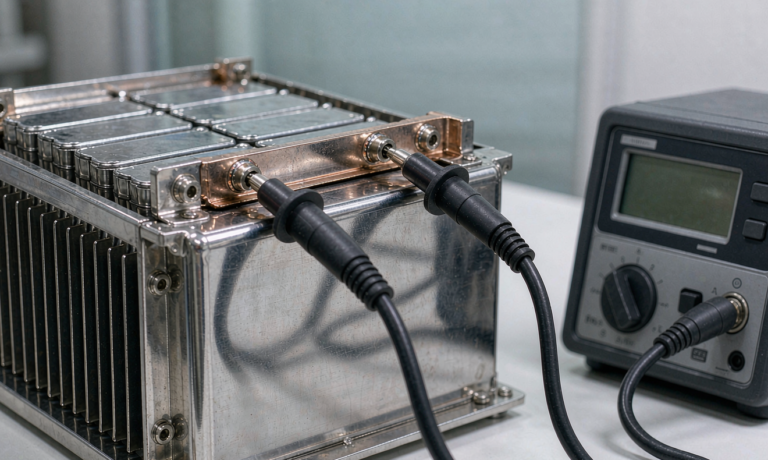
My procedure: stabilise the module at the test temperature for a minimum of four hours (not two — prismatic cells with aluminium housings have a long thermal time constant), charge to full per the manufacturer’s CCCV profile, rest one hour, then apply the constant-power load until the pack reaches the inverter’s true low-voltage cut-off, typically 1.75 V/cell-equivalent for legacy VRLA-compatible inverters or 2.5 V/cell for native lithium systems. I log cell-level voltages at 100 ms resolution, because the first cell to hit the floor sets the runtime, and that cell is almost never the one with the lowest capacity — it is the one with the highest DCIR.
DCIR itself I measure by a 10 s pulse at 2C from 50% state of charge, with the ohmic and polarisation components separated at the 100 ms mark. For a healthy 100 Ah LFP prismatic cell I expect roughly 0.6–0.9 mΩ at 25 °C, rising by a factor of 2.2 to 2.8 at 0 °C. That temperature multiplier is the single most useful number in UPS sizing, and I insist it appears in every datasheet we publish. Any credible custom battery solution for UPS duty should be quoted with a cold-temperature derating table, not a single 25 °C figure.
Safety and Compliance Testing: UN38.3, IEC 62133, IEC 62619 and UL 1973
Compliance is not a rubber stamp; each standard answers a different question, and UPS packs usually need several in combination.
- UN 38.3 (transport) — altitude simulation, thermal cycling, vibration, shock, external short circuit, impact/crush, overcharge and forced discharge. This is a shipping prerequisite, not a product-safety approval. Every module we ship carries a UN 38.3 test summary as required since 2020.
- IEC 62133-2 — cell and small-battery safety for portable applications. Relevant for the smaller rack modules and for any cell we qualify into the platform.
- IEC 62619 — safety requirements for secondary lithium cells and batteries in industrial applications, including UPS and stationary use. This is the one that governs most UPS modules, and it adds the propagation and internal-short-circuit requirements that IEC 62133 does not.
- IEC 62620 — performance and dimensional requirements for industrial lithium cells, which is where the standardised capacity and endurance test methods live.
- UL 1973 — batteries for stationary, vehicle-auxiliary and light-rail use; the North American gate for UPS and home energy storage-class equipment.
- UL 9540A — thermal runaway fire propagation methodology at cell, module, unit and installation level. Not a pass/fail standard but a data-generating one; fire officials increasingly ask for it before signing off a battery room.
- IEC 62485-5 — safety requirements for stationary lithium battery installations, covering ventilation, spacing and installation practice.
One practical note from the lab: overcharge testing per IEC 62619 must be run with the protection circuit deliberately defeated, and I always instrument the vent path with a shielded thermocouple plus a pressure transducer. LFP cells rarely go into violent runaway, but they do vent electrolyte vapour at around 120–150 °C internal, and the resulting deposits will short a poorly sealed rack connector months later. That is a field failure with a laboratory root cause.
Float, Calendar Life and Thermal Testing
Because a UPS pack floats for years, calendar ageing is the dominant degradation mechanism, and this is where most test programs are far too short. My accelerated protocol holds modules at the float set-point at 45 °C and 55 °C, with a full capacity and DCIR check every 30 days, then fits an Arrhenius model to project 25 °C and 35 °C behaviour. Three months of data at two temperatures gives a defensible ten-year projection; one month at a single temperature gives you a number you should not put in a warranty document.
Two hard-won findings worth passing on. First, float state of charge matters enormously: holding LFP at 100% SOC instead of 90% roughly doubled the calendar fade rate in my data set at 45 °C. That is why our BMS firmware floats UPS modules at approximately 3.35 V/cell rather than 3.45 V/cell, trading about 3% of nameplate runtime for a materially longer service life. Second, the cabinet, not the cell, usually sets the temperature. I have logged a 9 °C gradient between the bottom and top module in a sealed 42U rack with no forced airflow. Any lithium battery life projection that ignores in-cabinet gradients is optimistic fiction, so I now require thermal mapping of the populated rack as part of qualification.
BMS, Protection and Failure-Mode Testing
More UPS lithium deployments fail for integration reasons than for cell reasons. My integration test list, in the order I run it:
- Protection trip verification: confirm over-voltage, under-voltage, over-current, over-temperature and under-temperature-charge thresholds by driving the pack to each limit, with response time logged. Under-temperature charge protection is non-negotiable — charging LFP below 0 °C plates lithium metal and is a genuine safety issue, not just a warranty one.
- Load-step response: apply a 0 to full-power step in under 5 ms and verify the BMS does not nuisance-trip on the inrush. This single test has caught more firmware bugs than everything else combined.
- Parallel-string current sharing: with four modules in parallel, I measure per-string current during a 4C discharge. A spread beyond ±10% points to interconnect resistance imbalance, and I have traced a 22% imbalance to a single under-torqued busbar bolt.
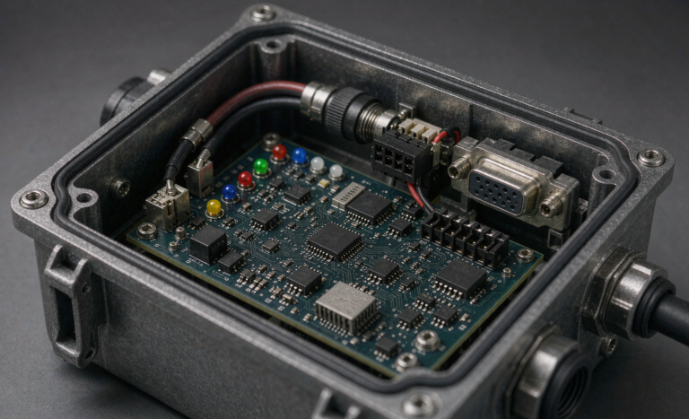
- Communications robustness: CAN or RS-485 traffic verified against the inverter’s protocol map, including behaviour on cable disconnect, and confirmation that the pack fails safe rather than fails silent.
- Recharge-after-event: measure recharge time to 90% after a full backup event. Many UPS specifications require 90% within 8–10 hours, and an undersized charger quietly violates this while every individual component still passes its own test.
Field Acceptance Testing and Documentation That Survives an Audit
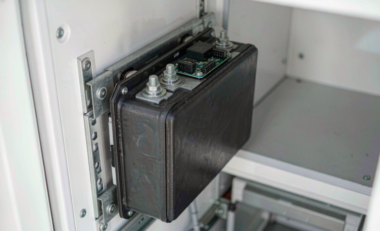
Factory validation proves the design; site acceptance proves the installation. My commissioning routine is deliberately short so that it actually gets done: verify all cell voltages within 30 mV at full charge, torque-check and thermal-image every power connection at full load, run one timed discharge at real load to at least 80% of rated backup time, confirm data logging into the building management system, and record ambient plus per-module temperature.
I then require the customer file to hold the UN 38.3 summary, the IEC 62619 or UL 1973 certificate, the pack-level test report with serial numbers, the commissioning discharge curve, and the recommended annual maintenance interval. When a pack underperforms in year four, that commissioning curve is the only thing that lets anyone distinguish a manufacturing problem from four years of a hot, poorly ventilated cabinet. The same discipline applies whether we are qualifying a stationary module or a high-rate drone battery pack — the traceability requirement does not change, only the duty cycle does.
Sound like a lot of work? It is. But a UPS battery only has to prove itself on the day everything else has already gone wrong, and there is no partial credit on that day.
Frequently Asked Questions
How is lithium battery testing for UPS systems different from testing a standard cycling pack?
The emphasis inverts. Cycling applications are validated primarily on cycle life at moderate rates; UPS packs are validated on calendar life at float plus short, very high-rate constant-power discharge. A UPS test plan must therefore prioritise accelerated calendar ageing, cold-temperature DCIR and constant-power runtime, and can devote comparatively little effort to deep-cycle endurance.
Which standards does a UPS lithium battery module actually need?
For most markets: UN 38.3 for transport, IEC 62619 (with IEC 62620 for performance) for industrial safety and performance, and UL 1973 for North America. UL 9540A propagation data and compliance with IEC 62485-5 installation requirements are increasingly requested by authorities having jurisdiction for battery rooms.
Why does my UPS pack deliver less runtime than the nameplate capacity suggests?
Three usual causes. The load is constant power, so current rises as voltage sags; the discharge rate is far above the C/3 condition at which capacity is rated; and the ambient temperature is below 25 °C, which raises internal resistance by a factor of two or more. Runtime should always be verified by constant-power test at the worst-case temperature, never calculated from amp-hours alone.
Can I test a lithium UPS module using my existing VRLA test equipment?
Partly. A conventional load bank is usable for the discharge itself, but you also need cell-level voltage logging, BMS data capture over CAN or RS-485, and a charger able to follow a CCCV lithium profile. Testing a lithium pack with VRLA cut-off voltages and no cell-level visibility hides exactly the imbalance problems the test is meant to find.
How often should installed UPS lithium batteries be retested?
I recommend continuous BMS trending plus an annual verification: cell-voltage spread at full charge, thermal imaging of connections at load, and a timed partial discharge. A full timed discharge to the specified backup duration every two to three years is appropriate for critical loads, scheduled during a maintenance window with an alternative power source available.
What float voltage extends UPS lithium battery life the most?
For LFP chemistry, floating around 90% state of charge rather than 100% substantially reduces calendar fade — in my accelerated data, roughly halving the fade rate at 45 °C. The cost is a small reduction in available runtime, so the pack should be sized with that headroom designed in from the start rather than recovered later by raising the float voltage.