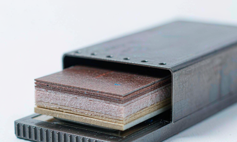
Semi-Solid State Battery DC Resistance
As a senior lithium battery engineer at Horizon Power, I spend a large share of my week characterizing cells that customers plan to build into drones, industrial packs, and grid buffers. One number that decides whether a semi-solid state battery will survive a real application is its direct current resistance, often shortened to DC resistance or DCIR. A pack can look excellent on an energy density slide and still fail on the bench because the semi-solid electrolyte and composite cathode add interfacial resistance that a liquid electrolyte would have hidden. In this article I explain what DC resistance is, why semi-solid state chemistry tends to run higher than a conventional lithium battery, how we measure it, and what design levers actually move the number.
What DC Resistance Tells You About a Cell
DC resistance is the effective ohmic and near-instantaneous polarization resistance a cell shows when you pull or push current. Unlike a slow charge or discharge that lets chemistry keep up, a short pulse exposes the path that current must travel: through the current collector, the composite electrode, the semi-solid electrolyte, the separator, and back out the other side. The voltage drop during that pulse equals current multiplied by DC resistance. For a drone battery that means the difference between holding pack voltage under a hard throttle and sagging into a protection cutoff. For an industrial pack it decides how many parallel groups you need to deliver a given peak power.
The practical consequence is simple. Two cells with identical capacity but different DC resistance will show very different power. The lower resistance cell stays cooler, holds a higher bus voltage under load, and needs fewer parallel groups to hit the same peak. That is why a custom battery solution almost always starts from a DC resistance target rather than a capacity target.
Why Semi-Solid State Batteries Run Higher Resistance
A semi-solid state battery sits between a liquid electrolyte cell and a true solid state cell. It keeps a small fraction of liquid solvent in a composite cathode and uses a semi-solid or gel-like electrolyte to bridge the electrode and the separator. That design raises ionic resistance in three places. First, the composite cathode is denser and less permeable than a standard coated electrode, so lithium ions travel a longer effective path. Second, the interface between the cathode particle and the semi-solid electrolyte is a contact point with finite conductance, and poor wetting there adds a stable interfacial resistance. Third, the separator or electrolyte layer itself has lower ionic conductivity than a thin liquid film.
In our internal data, a well-built semi-solid state pouch at 50 percent state of charge and 25 degrees Celsius typically shows a DC resistance roughly 15 to 40 percent higher than a comparable liquid electrolyte lithium battery of the same format. The gap narrows as the cell warms and as formation cycles improve wetting, but it does not disappear. Engineers who size packs by liquid-electrolyte rules of thumb will over-promise power and under-size thermal headroom if they ignore this.
How We Measure DC Resistance
The standard method is a hybrid pulse power characterization, sometimes called an HPPC pulse after the test that popularized it. You rest the cell, then apply a short discharge pulse, often 10 seconds at a C-rate such as 1C or 2C, record the immediate voltage step, then the slow relaxation slope. The immediate step divided by the pulse current gives the ohmic part, while the relaxation gives the polarization part. The sum is reported as DC resistance.
For production screening we follow IEC 62660-1 style pulse sequences and also run a 1C or 2C pulse for 10 seconds at several states of charge, typically 20, 50, and 80 percent. We log the voltage at the first second and at the tenth second. The first-second value captures the ohmic and fast polarization resistance, which is what matters most for peak power. We repeat the pulse after a rest so the cell returns to equilibrium. A six-pulse map across temperature points gives us the data we put into the pack model.
I want to separate DC resistance from AC impedance. AC impedance, measured with a small alternating signal, splits the cell into frequency-dependent parts such as contact resistance, charge transfer, and diffusion. It is excellent for diagnosis but it does not directly tell you the voltage sag a drone sees in a 2 second throttle burst. DC resistance is the field-relevant number, and it is what a custom battery solution should be specified against.
What Drives the Number
Five variables move DC resistance more than anything else. State of charge is the first: resistance is lowest near 50 percent and rises toward both ends of the window, especially below 20 percent where the cathode approaches its knee. Temperature is the second: every 10 degrees Celsius of warming roughly cuts resistance by 15 to 25 percent in the semi-solid chemistry we build, so a cold pack is a high-resistance pack. State of health is the third: as the cell ages, interfacial resistance grows faster than bulk loss, so an old pack sags more than its capacity reading suggests.
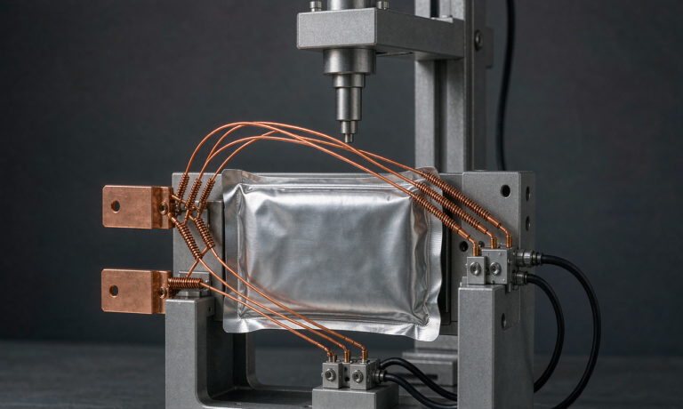
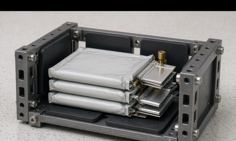
The fourth variable is stack pressure. A semi-solid state battery benefits from a steady clamping force because it keeps the composite cathode pressed against the semi-solid electrolyte. In our fixtures, raising pressure from loose contact to a modest 0.3 to 1.0 megapascal reduces DC resistance by 8 to 20 percent, but the benefit plateaus and excessive pressure damages the cell. The fifth is formulation: the conductive additive network, the electrolyte loading, and the cathode porosity set the floor. More conductive carbon and better wetting lower the floor, while a too-dense electrode raises it.
Typical Values and Design Levers
For the prismatic and pouch cells Horizon Power builds, a reasonable DC resistance target at 50 percent state of charge and 25 degrees Celsius is 0.8 to 2.5 milliohms for a large format cell and 3 to 8 milliohms for a small cylindrical cell, measured on the first-second 1C or 2C pulse. These are not universal constants; they depend on format, electrode area, and tab design. The design lever that pays off most is wetting: a formation process that fully wets the composite cathode and a stack pressure held in the optimal window will beat a chemistry tweak that looks better on paper.
When a customer asks for a custom battery solution, we translate the DC resistance target into parallel groups and cooling. If the application needs a 2 second peak at a fixed bus voltage, we size the parallel count so that the per-cell voltage drop stays inside the allowance, then add margin for cold start and end of life. Skipping that step is the most common reason a semi-solid state pack underperforms in the field.
Impact on System Design
DC resistance feeds directly into three system decisions. The first is bus voltage stability under load: the pack model uses per-cell resistance to predict sag, and the battery management system sets its protection thresholds from the same number. The second is thermal: power loss equals current squared times resistance, so a 20 percent higher resistance means a 20 percent higher I squared R heat at the same current, which changes the cooling requirement. The third is warranty: because resistance climbs with age, we specify the pack against its end-of-life resistance, not its fresh value, so the drone or machine still meets its power spec on the last day of the contract.
In short, DC resistance is the bridge between a promising energy density and a pack that actually works. A semi-solid state battery earns its place only when the higher resistance is designed around, not discovered in the field.
What is the difference between DC resistance and AC impedance?
DC resistance is measured with a real current pulse and reflects the total voltage drop you get under load, including ohmic and fast polarization parts. AC impedance uses a small alternating signal to separate those parts by frequency. DC resistance is the number that predicts field performance; AC impedance is the tool that explains why the number is what it is.
Why is DC resistance higher in semi-solid state batteries?
The composite cathode and semi-solid electrolyte add interfacial and ionic resistance that a free liquid electrolyte avoids. Wetting of the cathode, contact at the electrode electrolyte interface, and the conductivity of the semi-solid layer all add stable resistance. Good formation and stack pressure reduce but do not remove the gap.
How do you measure DC resistance of a battery cell?
We use a hybrid pulse power characterization: rest the cell, apply a 10 second 1C or 2C pulse, record the first-second and tenth-second voltage, divide the drop by the pulse current, and repeat at several states of charge and temperatures following IEC 62660-1 style sequences.
What is a good DC resistance value for a semi-solid state cell?
For large format prismatic or pouch cells at 50 percent state of charge and 25 degrees Celsius, a first-second 1C pulse resistance of 0.8 to 2.5 milliohms is a reasonable target. Small cylindrical cells run higher, around 3 to 8 milliohms. Format and tab design shift these values, so always compare same-format cells.
How does temperature affect semi-solid state battery DC resistance?
Resistance falls as temperature rises. In our builds, every 10 degrees Celsius of warming cuts DC resistance by roughly 15 to 25 percent. A pack that meets its power spec at 25 degrees Celsius may sag badly at 0 degrees Celsius, which is why cold-start margin matters.
How does stack pressure change DC resistance?
A steady clamping force keeps the composite cathode in contact with the semi-solid electrolyte. Moving from loose contact to a 0.3 to 1.0 megapascal window typically lowers DC resistance by 8 to 20 percent, with diminishing returns above the window and damage risk if pressure is excessive.
Further Reading
References