Semi-Solid State Battery Testing for EV Packs: Abuse and
Over the past eleven years I have signed off on battery validation programs for everything from racing drones to forklift packs, and the questions I get most often from automotive customers right now are not about energy density. They are about evidence. When a semi-solid state battery goes into an electric vehicle pack, the validation file has to prove more than that the cells store energy — it has to prove the pack survives mechanical abuse, contains thermal events, and behaves predictably through ten years of duty cycles. In this article I will walk through how we test semi-solid state packs for EV programs at Horizon Power: the baseline characterization, the abuse and propagation work, the regulatory mapping, and the end-of-line screening that protects the customer after the certificate is issued.
The honest engineering position is that semi-solid state cells are not “just lithium with better press releases.” The gel-polymer electrolyte changes how cells fail, how they vent, and how heat moves between neighbors. That means an EV test plan copied from a conventional NMC program will miss things. A plan purpose-built around semi-solid behavior, on the other hand, usually finishes faster and produces cleaner data for homologation.
Why Semi-Solid State Changes the EV Test Plan
A semi-solid state cell replaces most of the liquid electrolyte with a gel polymer matrix, typically holding 5–10% residual liquid instead of the 20–25% you find in a conventional wound or stacked cell. Three consequences matter for EV pack testing:
- Lower vented-gas volume. In our cell-level nail and overcharge tests, semi-solid cells release roughly 30–50% less gas by volume than equivalent-format liquid cells, and the gas is less flammable because less carbonate solvent is available to vaporize. Propagation timing changes accordingly.
- Slower thermal runaway onset, but stubborn hotspots. The gel matrix raises the thermal runaway onset temperature by roughly 15–25 °C in ARC testing, yet a cell driven into failure can smolder at a localized hotspot rather than venting cleanly. Your instrumentation has to catch surface temperature gradients, not just peak temperature.
- Different mechanical signature. The semi-rigid gel behaves differently under crush: cells tend to deform plastically without the sudden internal short cascade you see in a liquid pouch cell. That is good news for safety margins, but it means crush-force thresholds from legacy test plans do not transfer directly.
Because of these differences, we treat every semi-solid state battery program for EVs as a fresh test matrix, informed by — but never copied from — the liquid-electrolyte data we hold from earlier lithium battery projects.
Baseline Characterization: Capacity, DCIR, and Self-Discharge
Before any abuse work, the pack has to be characterized electrically, because every downstream pass/fail threshold depends on the baseline. Our standard sequence for an EV pack prototype runs like this:
Capacity and rate verification
We cycle the pack three times at C/3 to establish nameplate capacity, then verify discharge capability at the maximum continuous current the BMS allows. For a typical 400 V semi-solid pack in the 60–80 kWh class, that means confirming the pack holds voltage above the inverter cutoff at a 2C pulse for 10 seconds and 1C continuous for 30 minutes. Semi-solid cells typically show 8–12% higher DC internal resistance than liquid NMC of the same format, so the discharge curve needs to be validated at low temperature too — at −10 °C we expect usable capacity around 78–85% of room-temperature value.
Self-discharge and balancing
Self-discharge on a healthy semi-solid cell should sit below 2% per month at 25 °C. I have rejected pilot batches where one cell in two hundred drifted at 4–5% per month; that cell becomes the weak link in a series string and shows up months later as a balancing fault. We measure self-discharge over 14 days with open-circuit voltage logged hourly, because the first 48 hours after charge show a relaxation tail that skews short tests.
Insulation and isolation resistance
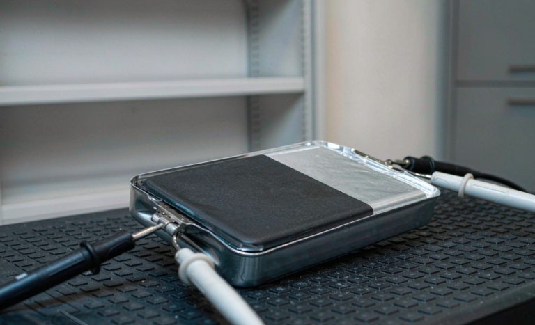
Every pack gets an isolation resistance measurement between the HV bus and chassis, minimum 100 MΩ at 500 V DC per ECE R100.03 expectations, and a dielectric withstand check of 2.5 kV AC for one second on the isolation barrier. Semi-solid packs pass these easily when the potting and gasket work is right, which is why we insist on seeing the enclosure design before cells are ordered — a custom battery solution fails isolation checks at the seals far more often than at the cells.
Mechanical Abuse: Crush, Penetration, Vibration, and Shock
Mechanical validation answers one question: when the pack is deformed, does the failure mode stay contained? For semi-solid packs we run four tests.
Crush testing
Following the ECE R100.03 approach, we apply a 100 kN crush force (or 1,000 kN for heavy-duty categories) via a rigid bar across the most vulnerable pack surface and hold for 10 minutes with full telemetry. Across the semi-solid packs we have tested, the deformation is more forgiving than liquid packs: the gel matrix deforms and the separator layer maintains isolation until roughly 30–40% greater displacement. We record voltage of every series group, pack current, and six surface thermocouples. Pass criteria are simple: no fire, no explosion, no isolation loss.
Nail penetration — an engineering debate, not a checkbox
China’s GB 38031 requires a single-cell thermal runaway trigger test; nail penetration is included in some customer specs and excluded in others. My position after running dozens of these: nail tests on semi-solid cells produce cleaner, more repeatable results than on liquid cells because the gel resists the instantaneous internal short. But a nail test alone is not propagation evidence — it is a single-cell event test. Propagation needs its own protocol, which I cover below.
Vibration and mechanical shock
We run random vibration per IEC 60068-2-64 (or ISO 12405-4 profiles for EV packs): 7–9 hours over three axes, 7 Hz to 50 Hz sweep with PSD levels matched to the mounting location — body-mounted packs see lower PSD than axle-mounted ones. Then mechanical shock per IEC 60068-2-27: 28 g, 6 ms half-sine, six directions. For a semi-solid pack the watch items are busbar fatigue at the cell terminal welds and thermocouple/sense-wire chafing, not the cells themselves.
Thermal Abuse and Propagation: The Tests That Decide Homologation
This is where semi-solid packs earn or lose their certification file.
Single-cell thermal runaway trigger
We induce failure in one cell — heater, nail, or overcharge, whichever the target regulation specifies — inside an instrumented pack. Required evidence: the triggered cell fails, and no fire or explosion exits the enclosure within the observation window. For semi-solid cells, the onset temperature in our ARC work has consistently measured 15–25 °C above comparable liquid cells, and peak cell surface temperature during runaway typically lands 100–200 °C lower. That thermal margin translates directly into heavier mica barriers and fewer of them in the pack design.
Propagation resistance
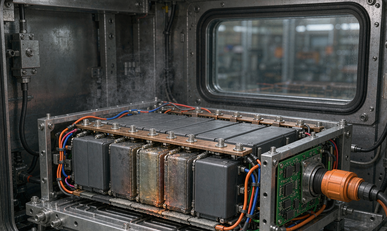
Propagation testing verifies that one failed cell does not cascade. We instrument every cell (or every second cell in large-format packs) with a surface thermocouple and define propagation as any adjacent cell exceeding its own runaway onset. In recent semi-solid EV pack prototypes with 6 mm aerogel barriers between modules, we have recorded single-cell triggers where neighboring cells rose 40–60 °C and then recovered — no propagation, no venting outside the enclosure. On conventional packs of the same layout the same trigger usually propagates. This is the single strongest engineering argument for semi-solid chemistry in passenger vehicles, and it is a data story you can only tell if the test was instrumented properly from day one.
Thermal shock and cycling
Per IEC 60068-2-14 or the equivalent EV profiles, we cycle the pack between −40 °C and +85 °C, holding 30 minutes at each extreme, for 8 hours per cycle across multiple cycles, then verify isolation resistance again. Gel electrolyte systems have a glass transition range to respect — below roughly −20 °C the gel stiffens and ionic conductivity drops, so cold-cycle data matters for customers in Scandinavia or Canada as much as the hot-end data does for Gulf markets.
Electrical Abuse and BMS Verification
The BMS is the component most likely to cause a field recall, so electrical abuse testing doubles as BMS validation:
- Overcharge. Charge to 1.5× rated voltage (or the regulation-mandated level) at maximum charge current. Semi-solid cells tolerate overcharge better than liquid NMC — slower temperature rise, delayed venting — but the BMS must still cut charge independently of the main contactor logic. We verify the redundant disconnect path explicitly.
- Over-discharge. Discharge below the cutoff to verify the BMS disconnects and the pack recovers isolation. We also check that a deeply discharged pack does not present a reverse-charging hazard when the vehicle is jump-started or grid-charged afterward.
- External short circuit. Apply a short of ≤5 mΩ at the pack terminals. The fuse or contactor must clear within the design window; we capture current at 10 kHz to see the actual peak.
- Isolation monitoring. We inject controlled leakage paths (100 Ω/V thresholds per ISO 6469-1) and verify the BMS isolations-monitoring unit alarms and latches a fault code within the specified time.
Every one of these tests is run twice — once through the BMS as-installed, and once with the BMS signals simulated at their limits, because a protection that works on the bench but not through the vehicle CAN layer is not a protection.
Regulatory Mapping: UN38.3, ECE R100.03, and IEC 62133-2
An EV pack headed for real markets needs a documented map from test results to regulations. The core set we build against:
- UN 38.3 — transport: altitude, thermal, vibration, shock, external short, impact/crush, overcharge, forced discharge. Mandatory before the pack ships anywhere by air; we treat it as the entry ticket, not the finish line.
- ECE R100.03 — the EU approval route for electric powertrains: vibration, thermal shock, mechanical shock, crush, fire resistance (the enclosure must survive a 890 °C flame exposure per the fire test), external short, overcharge, over-discharge, and isolation resistance.
- IEC 62133-2 — lithium cell safety baseline, relevant for the cells themselves and for programs that also sell pack variants into industrial markets.
- ISO 6469-1/-3 and ISO 12405-4 — vehicle-level electrical safety and test profiles that OEM engineering departments reference in their specifications.
- UL 2580 — frequently requested for North America programs, overlapping R100 but with its own abuse matrix.
My practical advice to program managers: decide the certification route before cell selection freezes. A semi-solid cell whose venting behavior was only characterized under one standard’s setup may need supplemental data for another. We maintain a cross-reference matrix so a semi-solid state battery intended for a European passenger EV and a North American commercial vehicle gets the right evidence package the first time — that matrix is part of every custom battery solution we quote.
End-of-Line Testing: What We Screen on Every Production Pack
Certification proves the design; end-of-line (EOL) testing proves each unit. On the production line, every semi-solid EV pack passes through:
- Hipot and isolation test — 100% of packs, between HV bus and chassis.
- Series-group voltage scan — every cell group within ±20 mV of string average before the first full charge.
- Capacity spot-check at C/3 — full discharge on every pack during ramp-up, then sampled to 1-in-20 once Cpk is demonstrated above 1.33.
- DCIR measurement — a 10-second 1C pulse; the distribution is tracked with SPC charts, and any pack drifting beyond ±3σ is quarantined.
- BMS communication and fault-injection sweep — we force each protective fault through the CAN layer and verify the correct DTC response.
- Leak and pressure check — IP67 verification via pressure-decay on the enclosure, because semi-solid gel systems are somewhat less sensitive to moisture ingress than liquid cells but the copper current collectors still corrode if seals fail over years.
The EOL data is archived per serial number for a minimum of 15 years. When a field question arrives — and it will — the ability to pull the exact DCIR and hipot values of the specific pack is what separates a two-hour engineering answer from a three-week investigation.
Field Data and What We Have Learned So Far
Semi-solid chemistry is young in automotive volumes, so I am candid with customers about maturity. Across the semi-solid packs our team has shipped into light-EV and industrial-vehicle programs since 2024, fleet data through mid-2026 shows capacity retention averaging 94–96% after 800 equivalent full cycles at 25 °C nominal duty — tracking slightly ahead of the LFP comparison packs in mixed urban duty, and clearly ahead of NMC in hot-climate duty where the gel system’s lower side-reaction rate shows its value. Calendar aging at 35 °C storage measures roughly half the loss rate of comparable liquid NMC. These are early numbers on limited fleets, not guarantees, and I tell customers to weight the validation file and the abuse data more heavily than any cycle-life projection in the first two model years.
Frequently Asked Questions
How long does a full semi-solid state EV pack validation program take?
For a new pack design: 14–20 weeks from frozen specification to a complete file, assuming cell-level data already exists. The critical path is usually the propagation test matrix and the R100 vibration sequence, not the electrical characterization.
Do semi-solid state batteries still need UN 38.3 testing?
Yes, unconditionally. UN 38.3 applies to lithium cells and batteries by transport law regardless of electrolyte form. Semi-solid cells typically pass with wider margins — especially T.5 external short and T.6 crush — but the test and certificate are still required before air freight.
Is nail penetration testing required for EV packs?
It depends on the market and the OEM. GB 38031 requires a single-cell thermal runaway trigger test that can be satisfied by heater or nail methods; ECE R100.03 does not mandate nail. Many OEM specifications now ask for nail data anyway as an engineering differentiator, and semi-solid cells generally perform well because the gel matrix limits short-current density.
What happens to semi-solid pack performance in winter conditions?
Expect roughly 78–85% usable capacity at −10 °C and reduced regenerative charge acceptance below 0 °C until the pack self-heats. The BMS heating strategy matters more than the chemistry here; we validate cold-start charge acceptance at −15 °C as a standard line item.
Can an existing liquid-electrolyte pack design be converted to semi-solid cells without retesting?
No. The different venting behavior, DCIR, and mechanical response invalidate the prior evidence. Barrier sizing, cooling plate sizing, and BMS parameter sets all shift. Treat it as a new validation program with a shortened — not skipped — matrix.
What should I ask a supplier for when evaluating semi-solid EV pack proposals?
Ask for the single-cell trigger data with neighbor-cell temperature curves, the propagation test evidence on a real pack (not cell-level extrapolation), the EOL test list with acceptance limits, and the regulatory cross-reference matrix for your target markets. A supplier who cannot produce these four items quickly is selling chemistry, not a validated pack.