Semi-Solid State Battery Testing for Robotics
Introduction
When a logistics robot, an autonomous mobile manipulator, or a warehouse pick-and-place arm goes offline because its battery failed, the cost is never just the cell. It is the stopped line, the missed SLA, and the engineer paged at 2 a.m. Over the last nine years building semi-solid state battery packs at Horizon Power, I have come to treat semi-solid state battery testing robotics programs as a discipline of their own — separate from the validation we run for drones or grid storage. A robotic duty profile is brutal in a specific way: short, violent discharge pulses, frequent partial cycles, and almost no tolerance for thermal runaway inside a crowded chassis.
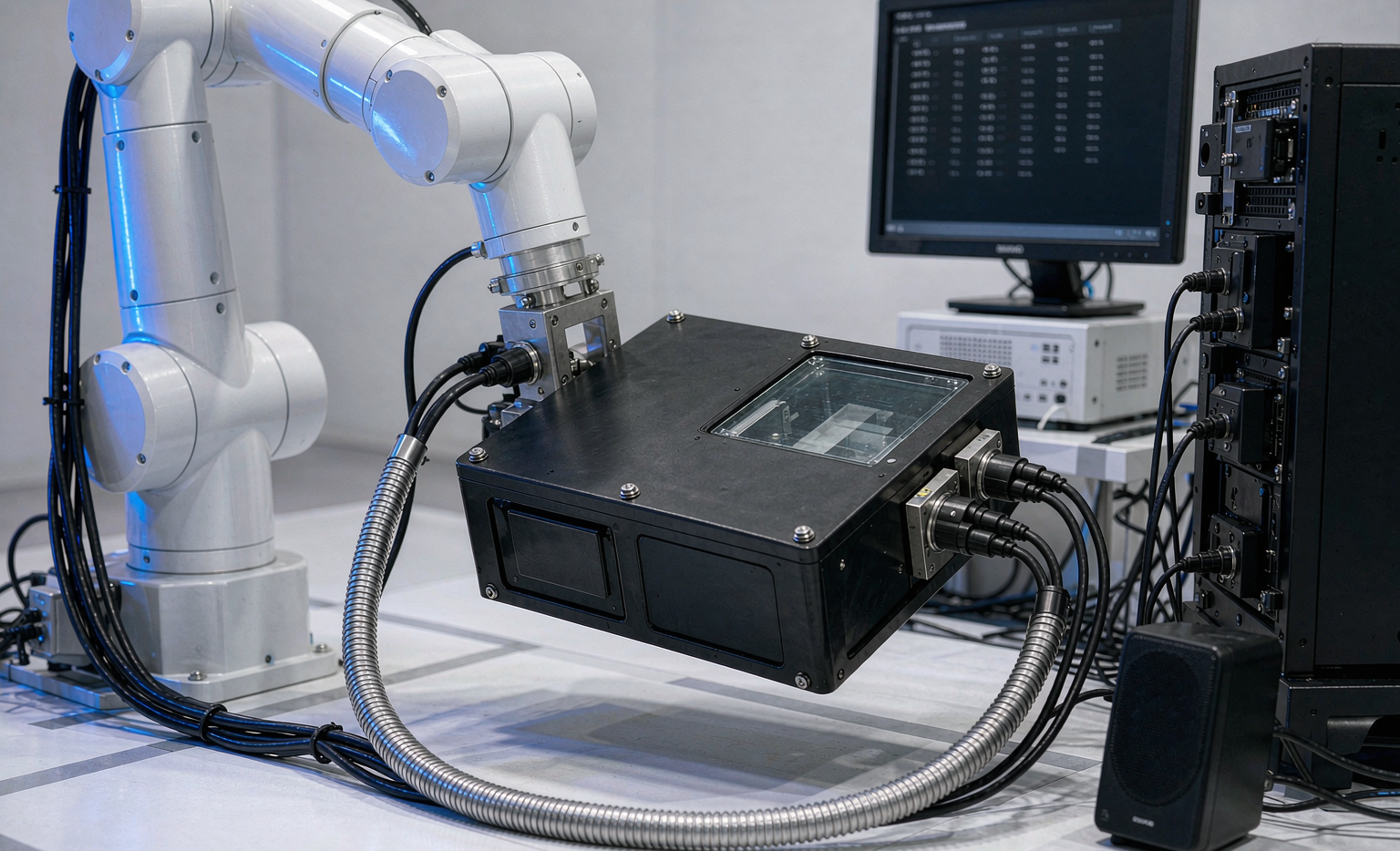
This guide walks through the exact test matrix my team uses before a semi-solid-state battery is cleared for a robotic platform. It is written for engineers who already know the basics of lithium chemistry and want the practical, standards-backed sequence that turns a promising custom battery solution into a field-proven pack.
Why Robotics Needs a Different Testing Playbook
A semi-solid state battery sits between a conventional liquid-electrolyte lithium-ion cell and a fully solid-state cell. At Horizon Power we run a quasi-solid electrolyte with roughly 5–15% retained liquid solvent, which lifts ionic conductivity to practical levels while removing the flammable bulk solvent that makes traditional cells dangerous. The result is an energy density of 300–400 Wh/kg — well above the 250–270 Wh/kg we see in quality NMC pouch cells — with a meaningfully safer abuse response.
Robots care about both numbers. Extra Wh/kg lets a mobile manipulator run longer between charges, and the safer abuse response protects the expensive actuators packed around the pack. But those gains are only real if the pack survives the robotic duty cycle, so our semi-solid state battery testing robotics flow starts from the load profile, not the cell datasheet.
Typical robotic loads are not steady discharges. They are 10–30C pulse bursts during acceleration, near-zero draw during a holding pose, and fast 1–2C recharge during docked idle. A test plan built around a calm 0.5C constant discharge would never see the weak cell that fails under pulse. That is why we characterize pulse behavior first, and why we record a real duty cycle from the customer’s robot rather than trusting a generic profile.
Electrical Characterization: Capacity, DCIR, and the Power Envelope
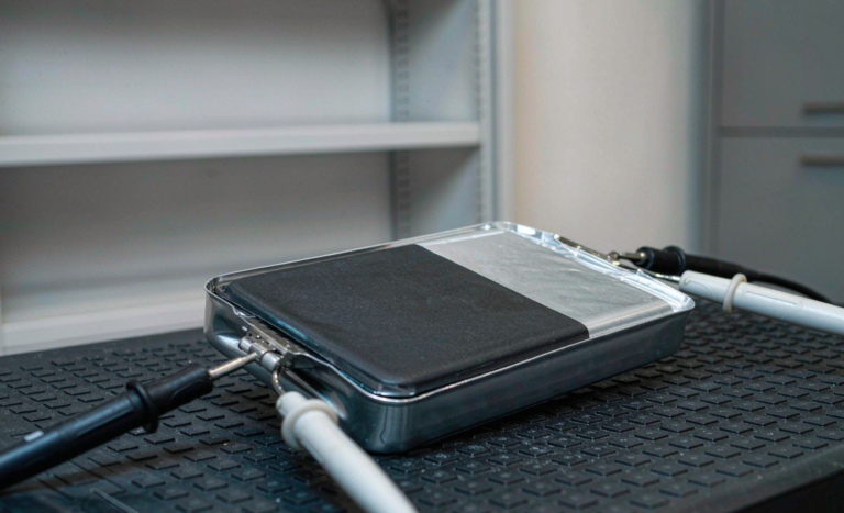
We begin with a formation and conditioning cycle, then baseline the pack at 25°C using a 4-wire Kelvin connection. Direct current internal resistance (DCIR) is measured with an HPPC-style pulse: a 10-second discharge pulse followed by a 10-second rest, sampled at 100 Hz. For our 24V and 48V robotic packs, a fresh semi-solid-state battery typically lands at 18–24 mΩ pack-level DCIR, and we bin cells to within ±3% so that series strings stay balanced in the field.
From the pulse data we build a power-envelope map: available voltage at 10C, 20C, and 30C against state of charge. This tells the robotics integrator exactly how much torque headroom exists at low SoC. We flag any cell whose DCIR drifts more than ±10% from the pack median — those are pulled before assembly. Capacity grading uses a 0.2C charge / 0.5C discharge to a 2.5V cutoff, repeated twice for stability, and every custom battery solution we ship carries a capacity bin label so the customer can trace the pack back to its test batch.
Thermal and Abuse Testing: UN 38.3 and Beyond
Safety qualification for a robotic lithium battery starts with UN 38.3, the transport and baseline safety standard every air- and ground-shipped cell must clear. Our sequence covers T.1 altitude simulation, T.2 thermal test (−40°C to +75°C), T.3 vibration, T.4 shock, T.5 external short circuit, T.6 impact, T.7 overcharge, and T.8 forced discharge. A semi-solid state battery passes these more comfortably than a liquid-electrolyte cell because the quasi-solid electrolyte suppresses the venting pathway that drives thermal runaway.
For stationary and industrial robotics we then layer IEC 62133-2 for the secondary cells, IEC 62619 for the industrial battery system, and UL 1642 / UL 1973 where the North American market requires it. We also run a nail-penetration and a 130°C hot-box test as internal abuse screens — for a semi-solid pack the goal is no flame and no projectile, only a controlled temperature rise.
Because many of our robotic customers ship globally, we align documentation with FAA and EASA expectations for lithium battery transport and onboard energy storage, even when the pack never leaves the ground. Treating aviation-grade paperwork as the default has saved several customers a painful re-certification loop.
Cycle Life and Calendar Aging Under Robotic Duty Profiles
Generic cycle-life numbers from a cell vendor are almost always measured at a gentle 1C, 100% depth of discharge, 25°C. A robot does not behave that way. Our semi-solid state battery testing robotics aging test replays a recorded duty profile — roughly 600 partial cycles per month of mixed pulse and rest — at 35–45°C pack temperature, which is what we actually measure inside a sealed robot base.
A well-built semi-solid-state battery delivers 1,000–2,000 equivalent cycles to 80% capacity under that profile, roughly double what we see from comparable liquid NMC packs in the same chassis. Calendar aging is tested separately: packs held at 60% SoC and 50°C for 12 weeks, then re-characterized. We publish the degraded DCIR and capacity as a derating curve so the integrator can size the pack with margin instead of guessing.
Mechanical Robustness: Vibration, Shock, and Ingress
A robot arm transmits vibration straight into the pack through its mounting points. We run random vibration per IEC 60068-2-64 across three axes, 8 hours per axis, and a 50g half-sine shock per SAE J2380 to mimic a dropped pallet or a hard dock. For outdoor and warehouse-floor robots we specify IP67 enclosures and validate with a 24-hour salt-spray corrosion screen on the housing.
Crucially, mechanical testing is never done on a cold pack. We heat the semi-solid state battery to its operating temperature first, because electrolyte stiffness changes the cell’s mechanical response and we want to find the failure, not hide it.
Sizing Margin: Turning Test Data Into a Field-Safe Pack
The point of all this testing is not a certificate on the wall — it is a sizing decision. From the power envelope and the aging derating curve we apply a two-layer margin: a 20% capacity reserve so the pack never hits true empty in the field, and a 15% DCIR headroom so voltage sag stays inside the robot controller’s undervoltage lockout. For a custom battery solution I also recommend a conservative state-of-health threshold — we trigger a service alert at 80% capacity rather than waiting for a hard failure. That single choice has eliminated the majority of unplanned robot downtime across our installed base.
Our In-House Validation Workflow at Horizon Power
For every custom battery solution destined for a robot, the workflow is fixed: (1) profile capture from the customer’s real robot, (2) cell and module-level electrical characterization, (3) UN 38.3 plus IEC abuse screening, (4) replayed-duty cycle-life and calendar aging, (5) mechanical qualification, and (6) a 72-hour burn-in at the pack level before shipment. Each step writes to a traceable test record, and only packs that clear all six are released.
This is the part of semi-solid state battery testing robotics that customers underestimate: the discipline of refusing a pack that passes nine of ten tests. In our lab, nine of ten is a rejection.
Frequently Asked Questions
What makes a semi-solid state battery safer than a regular lithium-ion cell?
The quasi-solid electrolyte removes most of the flammable liquid solvent, which is the fuel for thermal runaway. In our abuse screens a punctured semi-solid state battery shows a controlled temperature rise with no flame, whereas a conventional liquid-electrolyte cell of the same energy tends to vent and propagate.
How long does a full robotics test program take?
Electrical and mechanical characterization is usually two to three weeks. The cycle-life and calendar-aging replay adds eight to twelve weeks if you want real duty-profile data rather than vendor claims. We often ship a qualified pilot pack after the fast phase and confirm aging in parallel.
Can a semi-solid state battery handle 30C discharge pulses?
Yes, for short pulses. Our 24V and 48V robotic packs are characterized to 30C for 10-second bursts with DCIR staying within the power envelope. Sustained high-C discharge is a different question — that is where we would recommend a custom battery solution with a different cell format rather than pushing a standard pack.
Which standards do you certify against?
We qualify to UN 38.3 as the baseline, then IEC 62133-2 and IEC 62619 for the cells and system, with UL 1642 and UL 1973 available for North America. Documentation is aligned to FAA and EASA transport expectations so global shipments move without rework.
Is a semi-solid state battery worth the cost for a low-duty robot?
Not always. If the robot runs a calm 0.5C cycle in a climate-controlled lab, a quality lithium battery is the pragmatic choice. The semi-solid option pays off when you need a higher energy density in a tight chassis, higher pulse power, or a safer pack near people and expensive actuators.