Sodium-Ion Battery Dynamic Voltage Support and Ride-Through
Grid operators care about voltage as much as energy. A feeder that sags when a large motor starts, or rises when midday solar floods a rural line, needs reactive support that responds in milliseconds rather than minutes. In my work sizing storage for utility and industrial clients, I now regularly see sodium-ion battery dynamic voltage support written into interconnection requirements alongside peak shaving, because the chemistry handles this odd duty profile better than most buyers expect. This article explains what voltage support demands from a sodium-ion pack, how ride-through rules shape the design, and where the real engineering limits sit.
What Voltage Support Actually Asks of a Battery
Dynamic voltage support is reactive power work, not energy work. Active power in kilowatts does the useful job of running loads; reactive power does not travel to a load at all. It sloshes back and forth between the inverter and the grid, shoring up voltage. That distinction matters for a battery because reactive duty barely discharges the cells. What it does load is the inverter: switching losses, filter heating, and DC bus ripple all rise while the state of charge barely moves.
Most interconnection rules today follow IEEE 1547-2018, which defines a volt-VAR curve: when the point of connection falls below nominal, the inverter injects reactive power; when it rises above nominal, the inverter absorbs it. Category B settings default to roughly 44 percent of nameplate apparent power available for voltage support, and utilities can require full rated current at 0.9 power factor. I always tell clients to read the curve, not the headline. A system that delivers 1 MVar at 0.95 pu but folds at 0.85 pu will fail the commissioning witness test.
Why Sodium-Ion Chemistry Suits Reactive Duty
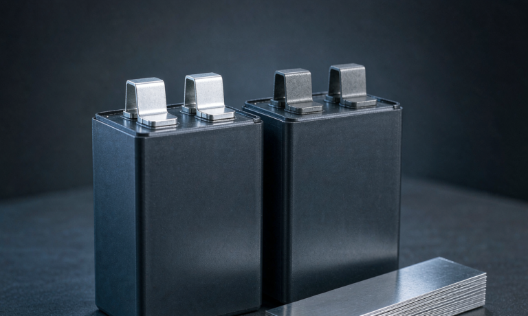
Three properties make a sodium-ion battery a comfortable fit for voltage work. First, internal resistance is low: prismatic cells in the 100 to 280 Ah class measure 1.0 to 2.5 milliohm, so the pack buffers inverter ripple without large voltage excursions on the DC bus. Second, the cell voltage window is wide. A layered-oxide cathode with a hard carbon anode operates across roughly 1.5 to 4.0 volts per cell, which gives the battery management system generous headroom to hold the bus during a transient.
Third, deep discharge does not hurt it. A sodium-ion cell uses aluminum on both electrodes, so there is no copper collector to dissolve at low voltage, and holding a pack at a low state of charge as a reactive reserve is routine practice. Add rate capability that retains roughly 85 to 90 percent of capacity at minus 20 degrees Celsius, and you get a pack that sits half idle, cold, and lightly cycled without complaint. Reactive duty at partial load raises cell temperature only 2 to 5 degrees Celsius above ambient in a pack rated for 1C continuous, which keeps calendar aging, not cycling, as the dominant wear mode.
Ride-Through Rules in Real Grid Codes
Voltage support is only half the requirement. The other half is staying connected through the disturbance you are supporting. Low voltage ride-through rules, written into IEEE 1547-2018 Category III, UL 1741 SB, EN 50549 in Europe, and NERC PRC-024 for the bulk system, all require the plant to remain online through a defined dip-and-recover envelope. A representative envelope asks the system to stay connected through a dip to 0.2 to 0.5 pu of nominal for a few hundred milliseconds up to about a second, and to inject reactive current in proportion to the depth of the dip while it lasts.
The subtlety is the recovery. When the fault clears, voltage rebounds and the inverter must swing immediately from injecting to absorbing reactive power, or trip. I have watched commissioning failures at exactly that point: the pack and inverter survive the dip, then the control firmware overshoots on recovery and the relay flags a flicker violation. Ride-through is a controls problem as much as a power problem, and it must be tested with a grid simulator that replays the actual utility curve, not a bench supply.
Sizing the Pack and the Inverter Together
Reactive capability is an inverter specification: a 1 MW power conversion system typically delivers 1.0 to 1.1 MVar. The battery’s job during voltage support is to supply losses, which run 2 to 4 percent of apparent power. The arithmetic is humbling. One MVar of support for ten seconds at 4 percent loss consumes about 0.1 kWh. Even a severe fault case, twice rated current for one second, draws well under 0.1 kWh. Energy is not the constraint; instantaneous current is.
Work the example. A 1 MW, 2 MWh sodium-ion system on an 800 V class DC bus draws about 1,250 A at rated power. Ride-through at twice rated current means 2,500 A through the bus and every string for a second or two. That asks the cells for a 2C to 3C pulse, which 100 to 280 Ah prismatic sodium-ion cells deliver without drama. A cell with 1.0 milliohm of internal resistance at 2C shows roughly 0.5 V of ohmic drop, and the BMS must expect that drop rather than log it as a fault. Thermal rise from a one second, 2C pulse stays under 1 degree Celsius, so no active cooling response is needed for the event itself.
BMS and Protection Design for Ride-Through Events
The battery management system is where most ride-through projects are won or lost. Current limits need short-duration tiers, for example three times rated for one second and one and a half times for ten seconds, coordinated with measured cell resistance so the limiter predicts bus sag rather than reacting to it. DC contactors must never open under a 2,500 A fault current; they weld. The inverter’s current control is the first line of defense, and the contactor only clears genuine internal faults.
Monitoring needs two thresholds. During a transient a healthy pack shows voltage spread well above its static value, so alarm on sustained spread above roughly 50 mV after the event, not on the spike itself. Keep 8 to 12 NTC sensors per pack on the terminals rather than the can, because surface sensing lags junction temperature by 10 to 30 degrees Celsius during fast pulses. Finally, log every ride-through event with a timestamp, dip depth, and injected current. Utilities increasingly request that log at annual review, and it is also the record that protects warranty claims when the system has done exactly what the interconnection agreement demanded.
Testing and Certification Path
Inverter-side conformance is settled law: IEEE 1547.1-2020 defines the ride-through and reactive capability test procedures, UL 1741 SB is the North American listing, and EN 50549 applies in Europe, with IEC 62116 covering anti-islanding. Battery-side safety runs through IEC 62619 for stationary applications and UL 9540A for thermal runaway propagation, while UN38.3 governs transport and requires shipping at 30 percent state of charge or less by air. For a complete grid-support system, IEC 62477-1 covers the converter safety case.
On new projects I ask for a witnessed ride-through demonstration with a grid simulator that replays the utility’s own curve from the interconnection agreement, plus a volt-VAR sweep that confirms reactive output at 0.95, 1.0, and 1.05 pu. At Horizon Power we ship those test reports with every grid-support system so the commissioning engineer can compare measured response against the contract curve before the utility witness arrives, which removes the most common source of schedule slip.
Frequently Asked Questions
Can a sodium-ion battery provide reactive power without discharging?
Yes. Reactive power shuttles between the inverter and the grid and delivers no net energy. The battery only supplies conversion losses, typically 2 to 4 percent of apparent throughput, so the state of charge stays nearly flat through voltage support events.
How long can the system ride through a voltage dip?
Most grid codes require several hundred milliseconds up to about one second, depending on category. A pack with 2C to 3C pulse capability and an inverter sized for twice rated current holds the bus through that envelope without cell damage.
Does voltage support duty shorten sodium-ion battery cycle life?
No measurable effect has been shown. Reactive duty does not cycle the cells, so the cycle counter barely moves. Calendar aging remains the dominant wear mode, which is why thermal management and storage state of charge matter more than support events.
What standards apply to sodium-ion battery voltage support systems?
IEEE 1547-2018 with IEEE 1547.1-2020 test procedures, UL 1741 SB in North America, EN 50549 in Europe, and IEC 62116 for anti-islanding. Battery safety follows IEC 62619 and UL 9540A, and transport requires UN38.3 with cells below 30 percent state of charge when shipped by air.
How does a sodium-ion battery compare with a lithium battery for this duty?
Both chemistries perform well. Sodium-ion brings lower internal resistance in many prismatic formats, stronger cold-weather response, and no copper collector to dissolve at deep discharge, which matters when you park reactive reserve at a low state of charge.
Do I need a grid-forming inverter for voltage support?
Not necessarily. Volt-VAR support works on grid-following inverters. Grid-forming mode becomes relevant when you also want black start capability or stability on weak feeders, and many sodium-ion systems are configured to switch between both modes.
Further Reading
References