Sodium-Ion Battery Testing for Microgrids: Grid-Forming Interoperability, Black-Start Verification, and Partial-SoC Cycling Endurance
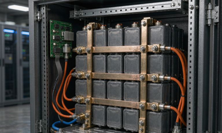
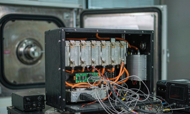
Over the last four years I have commissioned and validated more than thirty microgrid energy storage systems, and roughly half of the newer builds now use sodium-ion chemistry instead of lithium iron phosphate. Every time a client asks me why their sodium-ion battery project needs a different test plan than the LFP system they bought in 2021, I give the same answer: the cell behaves differently at low temperature, at partial state of charge, and during a black start, so the test plan has to prove those differences are handled correctly. This article is the checklist I actually carry to the site — the interoperability tests against grid-forming inverters, the black-start verification sequence, and the partial-SoC cycling endurance protocol that tells you whether a sodium-ion battery pack will still be healthy in year eight of a twenty-year microgrid.
Why Sodium-Ion Battery Testing for Microgrids Follows a Different Playbook
A microgrid is the least forgiving application in stationary storage. The battery must transition between grid-following and grid-forming modes without tripping, ride through islanding events, accept irregular solar charging, and occasionally cold-start an entire electrical island from zero volts. Lithium-ion test procedures written for behind-the-meter residential systems simply do not cover those transitions.
Sodium-ion chemistry adds its own quirks. The voltage curve is flatter in the mid-range but slopes steeply below about 20% state of charge, which changes how the BMS must estimate remaining capacity. Low-temperature charge acceptance is genuinely better than LFP — we routinely charge sodium cells at 0.5C at −10 °C with under 5% capacity impact — but the DC internal resistance rises sharply above 45 °C, so thermal test cases that pass for LFP can mask sodium-specific hot spots. When I plan sodium-ion battery testing for microgrids, I treat the chemistry differences as new failure modes to be proven out, not as marketing points.
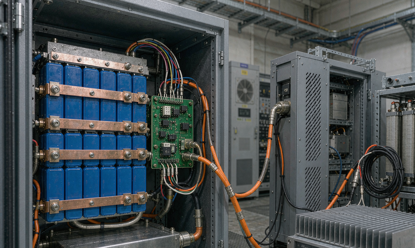
There is also a standards gap to close. The system-level framework for a microgrid battery is anchored by UL 1973 for the battery and UL 9540A thermal runaway data for the AHJ, while the interconnection behavior is governed by IEEE 1547-2018 and the microgrid controller performance is characterized under IEEE 2030.7 and IEEE 2030.8. None of those documents mention sodium-ion, because they are chemistry-agnostic. That sounds convenient, but it means every sodium-ion battery pack entering a microgrid must be qualified against the same acceptance criteria as lithium — and the test bench is where that proof happens.
Baseline Cell and Module Characterization Before Anything Connects to a Grid
I never let a pack go to interconnection testing until the module-level baseline is complete. The sequence I use looks like this:
- Capacity and DCIR mapping. Three full charge-discharge cycles at 25 °C, then DC internal resistance pulses at 10%, 50%, and 90% SoC. I expect cell-to-cell DCIR spread below 6% across a module; anything wider tells me the cell binning at the factory was loose and balancing duty will be high for life.
- Low-temperature charge verification. Full charge at 0 °C and −10 °C at 0.5C, followed by a recovery capacity check at 25 °C. Sodium-ion should recover above 97% of nameplate. If lithium plating analogs or hard carbon degradation show up, they appear here as a permanent 1–3% drop.
- High-temperature DCIR sweep. 45 °C and 55 °C pulse tests. This is the test most LFP-derived test plans skip, and it is exactly where sodium pack thermal design gets exposed.
- Self-discharge and balancing audit. Seven-day stand at 50% SoC, measuring per-cell drift. More than 2 mV/day of spread growth on a 20-cell module is a flag I investigate before shipment, not after installation.
For documentation, IEC 62619 gives the industrial safety baseline and IEC 62133-2 covers the cell-level requirements, while UN 38.3 governs transport. I keep all four reports in the microgrid commissioning dossier because insurers and AHJs increasingly ask for the full chain, not just the UL listing.
Grid-Forming Inverter Interoperability: Where Most Combinations Fail First
Interoperability testing is the phase I budget the most time for, because the battery and the inverter are usually from different factories and neither vendor tested the exact combination shipped to site. A grid-forming inverter draws real current from the DC bus with a ripple signature that varies by control architecture — some virtual synchronous machine implementations pull low-frequency oscillating current at twice the fundamental frequency, and a stiff battery with fast current limiting can interact badly with that.
My interoperability matrix has five rows, and I run all of them at 25%, 50%, and 90% SoC because sodium-ion DCIR shifts across that window:
- Steady-state charge and discharge at rated power for 60 minutes, watching cell temperature spread and DC bus ripple current against the BMS ripple rating.
- Mode transitions. Grid-following to grid-forming transitions triggered by simulated utility loss, verifying the battery responds to the inverter’s reactive power demand within the IEEE 1547-2018 voltage ride-through envelope.
- Frequency response. Frequency sweep tests where the inverter injects or absorbs power per a simulated droop curve, checking the BMS does not trip on transient current spikes. I have seen BMS over-current thresholds set too tight trip at 1.2× rated current for 200 ms — technically within rating, but enough to drop a microgrid during a fault-clearing event.
- Communication integrity. CAN or Modbus mapping audit between BMS and inverter, verifying every alarm and limit actually propagates. On one project the inverter ignored the BMS “derate” message entirely and charged at full current through a thermal warning — that defect was invisible until we forced the condition in a test.
- IEEE 1547-2018 conformance at the AC point. Voltage and frequency ride-through, active power restoration ramp rates, and unintended islanding behavior, verified with a grid simulator rather than trusted from the inverter vendor’s certificate, because the certificate was issued with a different battery.
The deliverable is a signed interoperability report naming the exact BMS firmware version and inverter firmware version. When either vendor ships an update later, we re-run the matrix rows that could be affected. Skipping that retest has cost two of my clients unplanned outages.
Black-Start Verification: The Test You Hope You Never Need
Black start is the defining microgrid battery test, and sodium-ion handles it well if the system is engineered and verified for it. The scenario: the grid is down, the PV inverters are asleep because there is no grid to synchronize to, and the battery must energize the microgrid bus from zero so the PV plant can rebuild.
The verification sequence I run looks simple on paper and takes a full day to execute properly:
- Precondition checks. Confirm the pack SoC is within the black-start window the design assumed — usually above 30% for sodium, because the steep voltage slope below 20% SoC narrows the usable cranking energy.
- Cold bus energization. Close the battery contactor into the transformer and inverter input, and record the inrush profile against the BMS short-circuit current rating. A 500 kVA transformer magnetizing inrush can hit 6× rated current for a few cycles; the BMS must not interpret it as a fault.
- Grid-forming build-up. Verify the inverter establishes voltage and frequency within its specification, then stage loads in the documented sequence — usually house loads first, then motor starts, then PV synchronization.
- Motor-start stress case. The largest motor on the island — a well pump or an HVAC compressor — starts while the battery is the only source. I record voltage dip at the battery terminals and confirm the BMS undervoltage alarm margin held.
- PV re-synchronization. Confirm the PV inverters detect a stable grid-forming source and ramp in smoothly without pulling bus frequency out of bounds.
We repeat the full black start at 25 °C and once more with the battery enclosure conditioned to 0 °C. Sodium-ion’s cold-cranking behavior is one of its genuine advantages — I have executed black starts at −15 °C with L-cells that LFP would have refused — but “should work” is not an engineering result. The test record is what the operations team relies on during a real outage at 3 a.m.
Partial-SoC Cycling Endurance: The Test That Predicts Year-Eight Health
Microgrids rarely cycle batteries from full to empty. The daily profile floats between roughly 35% and 85% SoC as solar charges through the day and loads discharge through the evening. Calendar-plus-cycling degradation in that partial-SoC window is the single best predictor of long-term capacity retention, and it is also where sodium-ion diverges most from lithium-ion test assumptions.
My endurance protocol runs a representative microgrid duty cycle — 1 cycle per day, 50% depth of discharge centered at 60% SoC, with a weekly full-cycle calibration — on a sample module at 25 °C and a second at 40 °C, for at least 1,000 cycles before handover, continuing in the lab afterward as a companion cell. Acceptance is simple: under 5% capacity fade and under 15% DCIR growth at 1,000 cycles. Sodium-ion platforms I have tested in this window typically land at 2–4% fade, which is competitive with the best LFP data I have seen for the same profile.
Two sodium-specific observations from that work. First, resting at high SoC is harder on these cells than cycling — modules held at 100% SoC at 40 °C fade measurably faster than cycled modules, so the microgrid controller should cap float voltage and the test plan must include a 30-day 100% SoC float case. Second, the flat mid-voltage curve means coulomb counting drifts more than on LFP unless the BMS recalibrates against a full cycle periodically; the endurance test verifies the recalibration actually corrects the drift rather than accumulating it.
| Test | Condition | Acceptance |
|---|---|---|
| Partial-SoC cycling | 50% DoD @ 60% SoC, 1,000 cycles, 25 °C | <5% capacity fade |
| Hot cycling | Same profile at 40 °C | <8% fade, no thermal drift |
| Float stand | 30 days at 100% SoC, 40 °C | <2% irreversible loss |
| Cold charge | 0.5C at −10 °C, then recovery check | ≥97% nameplate recovery |
| DCIR growth | Pulse test at 50% SoC after cycling | <15% growth vs. baseline |
Safety, Transport, and the Thermal Runaway Evidence Package
No microgrid battery reaches interconnection without a thermal runaway evidence package, and for sodium-ion the AHJ conversation is still new enough that the data has to be presented carefully. I compile UL 9540A test data at cell, module, and unit level, IEC 62619 abuse results (short circuit, overcharge, thermal abuse, crush), and the BMS protection verification record covering every alarm and trip point with measured response times.
The honest engineering picture: sodium-ion cells carry less energetic electrolyte and have shown lower peak heat release in the tests I have reviewed, which is a real advantage, but vented gas composition still requires proper enclosure venting design, and a sodium fire is not “non-flammable” as some marketing claims suggest. The UL 9540A data — heat release rate, gas composition, propagation behavior — is what the fire marshal reads, so I make sure it exists at all three levels before I put my name on the commissioning report.
Transport wraps the package: UN 38.3 for the cells and packs, with state-of-charge limits for shipment (we ship sodium modules below 30% SoC), plus the correct classification paperwork. Every sodium-ion battery pack I ship to a microgrid site carries that dossier, because customs and site inspectors both ask.
Field Commissioning: Turning Bench Data Into a Signed Microgrid
Bench results earn you the right to commission; they do not replace site verification. My field commissioning checklist for a sodium microgrid battery runs about forty items, and the critical ones are these:
- Receive-and-inspect. Open-circuit voltage within 50 mV of the shipping records, torque check on every busbar to the documented value, insulation resistance test on the DC system.
- Baseline capture. Record module capacity, DCIR, and balancing state at the site, at site temperature — this becomes the year-zero reference for every warranty conversation later.
- Protected-mode functional tests. Run every BMS protection (over-voltage, under-voltage, over-current, over-temperature) with controlled stimulus and log the actual trip point and response time. Factory test records are not enough; shipping damage and firmware mismatches both surface here.
- Full microgrid island test. Intentional islanding, load step rejection, PV transition, and one complete black start witnessed by the operations team, with all data logged.
- 72-hour soak. Three full daily cycles with the real load profile, watching SoC estimate convergence, thermal spread across the rack, and any communication faults. I do not hand over a site that has not run three clean consecutive days.
Only then does the system move from commissioning to operations, with the test dossier — cell certificates, UL 9540A package, interoperability matrix, black-start records, and the soak log — delivered as a single indexed document set.
What I Would Tell Anyone Specifying Their First Sodium Microgrid Battery
If you are writing the specification for your first sodium-ion microgrid battery, ask vendors for five things before you compare prices: their partial-SoC cycling data at 1,000 cycles minimum, their measured low-temperature charge curve, their grid-forming interoperability matrix with named inverter partners, their UL 9540A package, and their black-start test record from a comparable system. A vendor who can produce all five has done the engineering; a vendor who sends back a brochure has not.
Sodium-ion is not a downgrade from lithium in this application — in cold climates and in systems that float at partial charge most of their life, it is arguably the better chemistry. But the benefits are only real if the testing proves them at the system level, with the exact BMS, inverter, and controller combination that ships to site. That is the whole discipline of sodium-ion battery testing for microgrids: trust the datasheet enough to start, and verify everything that matters before the utility ever drops out.
Frequently Asked Questions
How long does sodium-ion battery testing for a microgrid project take?
Plan for four to eight weeks from module receipt to signed commissioning, depending on how much of the endurance data already exists. Cell and module characterization takes about two weeks, interoperability testing three to ten days, and the black start plus 72-hour soak roughly a week on site. The partial-SoC cycling endurance test to 1,000 cycles runs in parallel and usually continues after handover as a companion module.
Can a sodium-ion battery black-start a microgrid in freezing conditions?
Yes, and this is one of sodium-ion’s genuine advantages. I have executed verified black starts with the pack conditioned to −15 °C, where comparable LFP systems would refuse the discharge or deliver sharply reduced cranking energy. The test still has to be run and documented at the low temperature, because the BMS undervoltage margins and inverter inrush response must be verified, not assumed.
Which standards apply to sodium-ion batteries in microgrid energy storage?
The core set is UL 1973 and IEC 62619 for battery safety, UL 9540A for thermal runaway data required by most AHJs, UN 38.3 for transport, IEC 62133-2 at the cell level, and IEEE 1547-2018 for the interconnection behavior at the AC side, with IEEE 2030.7 and 2030.8 covering the microgrid controller. All are chemistry-agnostic, so sodium-ion must meet the same acceptance criteria as lithium.
Why is partial state of charge cycling tested separately from full-cycle testing?
Because microgrid duty cycles rarely use the full SoC window. Degradation mechanisms at partial SoC — especially long float periods at high charge — differ from full-depth cycling, and sodium-ion in particular ages faster resting at 100% SoC than it does cycling. A test plan that only does full cycles will significantly overstate the real service life of a microgrid battery.
Do grid-forming inverters need special configuration for sodium-ion battery packs?
The inverter does not care about the chemistry, but it does care about the BMS voltage limits, current limits, and communication map — and those differ between sodium and lithium packs. The interoperability matrix verifies charge and discharge behavior, mode transitions, frequency response, and alarm propagation with the exact firmware versions installed, at several SoC points.
How often should microgrid battery testing be repeated after commissioning?
I recommend an annual validation: capacity check against the year-zero baseline, DCIR pulse test, protection trip verification on a sampled basis, and one witnessed black start. Sites with critical loads usually add a semi-annual communication and derate-response audit, because firmware updates on either the battery or the inverter can silently break alarm propagation.