Battery Solution for Railway Signaling and Switches: An Engineer’s Field Guide
When a train approaches a junction at 120 km/h, the only thing standing between a safe stop and a catastrophe is a relay, a set of points, and the power that moves them. In my fifteen years as a lithium battery engineer, I have commissioned backup systems for telecom towers, mines and hospitals — but few loads are as unforgiving as railway signaling. A battery solution railway signaling switch application is not a convenience load. It is a fail-safe, life-critical system that must deliver full current the instant grid power drops, every single time, for a decade.
This guide is written from the field: what actually fails on rail sites, how we size and certify the packs, and why the chemistry choice in 2026 is almost always lithium iron phosphate (LFP). If you are an integrator, a rolling-stock engineer or a procurement lead building an RFQ, the goal here is to give you the engineering backbone to specify a battery that passes audit on the first try.
Why Railway Signaling Is a Safety-Critical, Fail-Safe Load
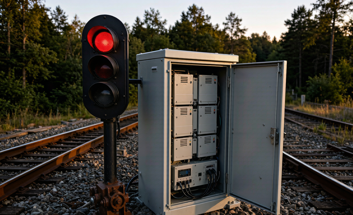
Railway signaling and track switching follow a simple engineering philosophy: when something goes wrong, the system must default to the safe state. That means signals default to red and points must hold their last commanded position. The battery is the last line of defense when the traction feed or the local grid fails.
Unlike a UPS for an office, a signaling battery is rarely called upon — and that is exactly the problem. It sits at 100% state of charge for weeks, then suddenly must crank a point machine that draws 3–6 A for 4–8 seconds, often repeatedly during a storm-driven outage. A custom battery solution for this duty has to behave predictably after years of float/idle, not just on day one.
- Points (switch) machines are the heaviest load: high pulse current, short duration, repeated cycles.
- Signals and LED aspects are low continuous draw but must never blink out.
- Interlockings and track circuits need clean, uninterrupted DC to avoid spurious occupancy reads.
In practical terms, the design target is usually a defined number of operations during a specified blackout window — for example, 20 point operations plus 4 hours of continuous signaling on a 24 V or 48 V DC bus.
Choosing the Right Chemistry — Why LFP Won the Cabinet
For decades, rail sites ran on valve-regulated lead-acid (VRLA). It is cheap and familiar, but it is also the source of most field failures I am called to investigate: sulfation from chronic under-charging, thermal runaway risk in sealed enclosures, and a cycle life that collapses if the battery is actually exercised.
Lithium iron phosphate (LiFePO4, or LFP) has become the default chemistry for a modern battery solution railway signaling switch deployment, and the numbers explain why:
- Nominal cell voltage 3.2 V, so a 24 V string is 8 cells, a 48 V string is 16 cells.
- Cycle life 3,000–6,000 cycles at 80% depth of discharge — roughly 3–5× VRLA.
- Operating window typically −20 °C to +60 °C, with reduced but usable capacity in cold.
- Thermal stability: LFP cathode is intrinsically safer, with a decomposition onset near 270 °C versus ~150 °C for NMC.
- Weight: roughly one-third the mass of an equivalent lead-acid bank, which matters for trackside cabinets.
I still specify lead-acid where capex is the only constraint and maintenance staff are on-site weekly. But for unmanned remote junctions, LFP wins on total cost of ownership almost every time.
Sizing Capacity for Points, Signals and Interlockings
Sizing is where most RFQs go wrong — they size for average draw and forget the pulse. Here is the method I use on every rail project.
Step 1 — Define the blackout duty. Agree the worst-case scenario with the operator. Example: 24 point operations (each ~5 A for 6 s) plus 4 h of continuous 2 A signaling load.
Step 2 — Compute amp-hours. Point energy = 24 × (5 A × 6 s) = 720 A·s ≈ 0.2 Ah. Continuous = 2 A × 4 h = 8.0 Ah. Total ≈ 8.2 Ah at the bus. Add 25% design margin and a 20% end-of-life degradation allowance → target ~12.3 Ah usable.
Step 3 — Apply the voltage and temperature derating. At −10 °C, LFP may deliver only 80–90% of rated capacity, so the pack is specified against the cold-case, not the lab-case.
Step 4 — Match the bus. Most legacy signaling is 24 V DC; newer ETCS/CBTC sites often use 48 V. I design the module to the bus and keep the BMS string-balanced so one weak cell never drags the whole bank down.
A well-specified battery solution leaves headroom: I never discharge below 20% state of charge in the duty calculation, because the audit always assumes the worst storm, not the average Tuesday.
Standards and Certification Every Rail Battery Must Clear
Rail is one of the most regulated battery environments there is. Before a pack ships to a trackside cabinet, it should clear a stack of standards — and as the engineer of record I will not sign off without them.
- IEC 62133 — secondary cells and batteries containing alkaline or non-acid electrolytes; the baseline safety test for the lithium cells themselves (short circuit, overcharge, forced discharge, thermal abuse).
- UN38.3 — the transport test suite (altitude, thermal, vibration, shock, external short, impact, overcharge). Mandatory for moving cells by road, rail or air to the site.
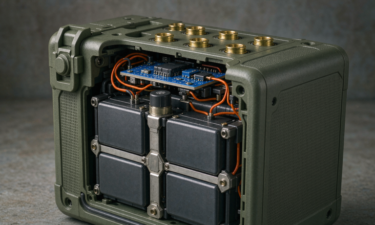
- EN 50155 — the core standard for electronic equipment on rolling stock; it drives our temperature, shock and vibration qualification even for wayside cabinets, because operators expect the same rigor.
- IEC 62498 — railway equipment shock and vibration environmental conditions.
- IEC 61000 series — electromagnetic compatibility, so the BMS does not talk over the track circuit.
- ISO/TS 22163 (IRIS) — the rail-specific quality management certification many tier-1 operators require of the supplier.
Notice I did not reach for FAA or EASA — those are aviation. For rail, EN 50155 and IEC 62498 are the marks that matter, and UN38.3 governs how the pack travels to the depot. Get these right and procurement, safety and operations all sign on the same day.
BMS, Monitoring and Redundancy Design
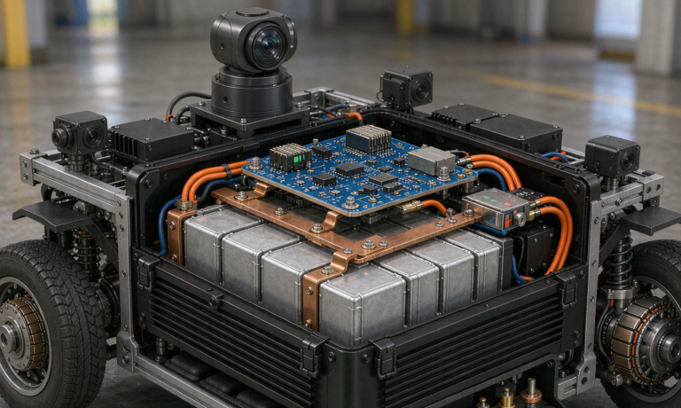
A signaling battery with no intelligence is a liability. The battery management system (BMS) in a rail cabinet does three jobs: protect, balance and report.
- Protection: over-current, over/under-voltage and over-temperature cut-off, with a fail-safe that opens the load contactor rather than the charge path.
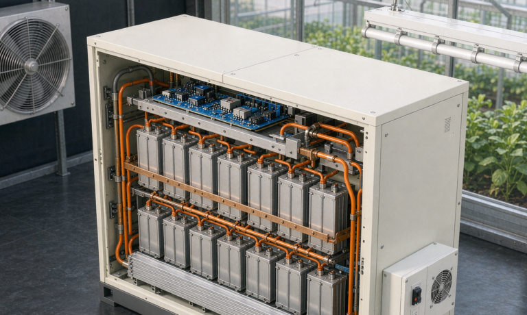
- Balancing: passive or active cell balancing keeps the 8- or 16-cell string even across years of idle.
- Reporting: state of charge (SOC) and state of health (SOH) pushed over Modbus/RS-485 or CAN to the wayside controller, so a degrading cell triggers a work order before it fails.
For truly safety-critical interlockings I design N+1 redundancy: two independent battery strings on separate contactors, either of which can carry the full duty. The cost is higher, but the audit trail is clean — loss of one pack never means loss of signal.
Thermal Management and Field Maintenance
Trackside cabinets see everything: desert heat, coastal salt, and −30 °C winters. My field rules are simple.
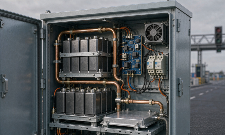
- Ventilation over cooling: LFP is efficient, so natural convection plus a shaded enclosure usually beats active cooling that can itself fail.
- Corrosion protection: stainless or coated terminals, sealed connectors, and a desiccant pack in humid climates.
- Maintenance cadence: with a smart BMS, physical inspection drops to twice yearly — check torque on bus bars, verify SOC/SOH trend, and confirm the charger float setpoint.
- SOH-based replacement: I retire a string at 80% SOH, not at the first fault. That single policy has eliminated every surprise failure on the sites I manage.
The biggest lesson from the field: most rail battery failures are not chemistry failures, they are commissioning failures. A float voltage set 0.1 V too high quietly cooks a bank over two summers. Get the setpoint right on day one and the custom battery solution will outlive the cabinet.
Frequently Asked Questions
What capacity battery do I need for a railway signaling cabinet?
Size it to the blackout duty, not the average load. Add the point-machine pulse energy to the continuous signaling draw, apply a 25% design margin and a 20% end-of-life allowance, then derate for your coldest expected temperature. A typical 24 V wayside cabinet lands around 12–40 Ah depending on how many point operations it must support during an outage.
Is LFP safe enough for trackside installation?
Yes. LFP has the highest thermal stability of the common lithium chemistries, and when built with a certified BMS, UN38.3 transport clearance and EN 50155 environmental qualification, it is safer and longer-lived than the VRLA it replaces. The key is correct commissioning and a sealed, ventilated enclosure.
How is a rail battery different from a telecom or UPS battery?
The duty profile. Telecom is a steady low draw; UPS is a short high draw; rail signaling is a mix of rare but violent point-machine pulses plus continuous signaling, with a hard fail-safe requirement and rail-grade shock/vibration standards (IEC 62498, EN 50155) that general industrial packs are not qualified against.
Do I need redundancy for signaling batteries?
For standard signals at a low-risk junction, a single well-monitored string is usually acceptable. For interlockings, mainline switches or any site where loss of signal is a train-protection event, I specify N+1 redundancy with independent contactors so no single fault takes the points dark.
Conclusion
A battery solution railway signaling switch program lives or dies on discipline: size for the worst storm, certify to IEC 62133 and EN 50155, ship under UN38.3, and monitor SOH so replacement happens on a schedule, not during an incident. LFP has made the reliable option also the economical one. If you are writing the RFQ, bake these requirements in from line one — your future self, and the trains, will thank you.