
Drone Battery Design for Mapping UAVs
I am Karl Huang, Senior lithium battery Engineer at Horizon Power, and most of the mapping projects that land on my desk start the same way: a survey team sends me a photo of the bay in their airframe and asks what will fit. That is the wrong first question. A mapping drone battery is not a shape you fill — it is the last physical expression of a survey specification, and every millimetre, milliohm and gram in it should be traceable back to a line item in that specification.
This article walks through the drone battery design process I actually use for mapping UAVs, in the order the decisions have to be made. It is deliberately a design article, not a performance or cost article: the output here is a set of engineering deliverables — a topology diagram, a DCIR budget, a mounting scheme, a thermal path, a BMS interface and a qualification plan — rather than a number of hectares or a price per flight.
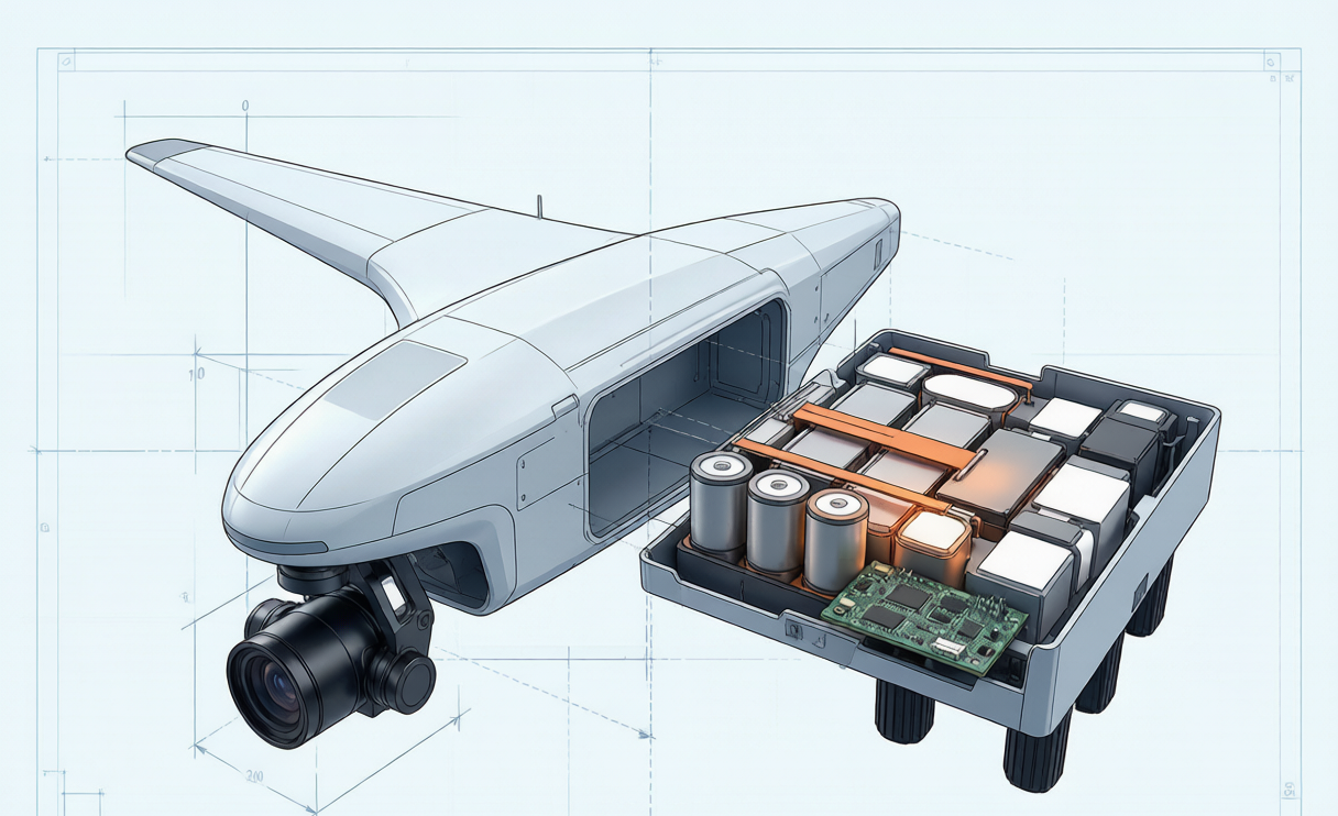
Why Mapping UAV Battery Design Starts With the Survey Spec
A mapping UAV has a duty cycle almost nobody else has. It flies long, straight, low-current lines at a nearly constant power level, turns at the end of each line, and does it with a sensor payload that hates electrical noise and mechanical vibration. Compare that with a racing or delivery airframe: those packs are designed around pulse power, 6–9C takeoff spikes and thermal recovery between sorties. A survey pack lives at 0.5–1.5C for 40–60 minutes at a stretch.
That single fact cascades through the whole design. It means the pack is energy-limited, not power-limited, so I spend my mass budget on Wh/kg rather than on C-rate. It means the internal resistance target is set by voltage stability during the shutter and RTK window, not by hover thrust headroom. And it means the mechanical design — where the pack sits relative to the centre of gravity, how it is isolated from the airframe, how quickly a field crew can swap it — carries as much weight in the design review as the cell datasheet.
So the first deliverable of a drone battery design is never a cell choice — it is a written design input sheet.
Step One: Convert the Mission Into Four Design Numbers
I compress a mapping mission into four numbers before touching a cell catalogue:
- Usable energy per sortie (Wh). Derived from cruise power × line time, plus turns, plus payload. A 6 kg VTOL surveying at 18 m/s draws roughly 0.74 kW in cruise; a 56-minute block is about 690 Wh, plus 40–60 Wh for VTOL transitions.
- Reserve fraction. I design to 25–30% unused state of charge at landing to satisfy FAA Part 107 and EASA SORA operational margins. That 690–750 Wh mission therefore needs roughly 1.0–1.06 kWh installed.
- Peak and pulse current. For a survey airframe this is the VTOL transition or a go-around, typically 2.5–3.5C for 5–15 seconds — modest, but it sets the busbar and connector sizing.
- Physical envelope and swap cadence. Bay dimensions, allowable mass, CG window, and how many times a day the pack is mated and de-mated (this drives connector plating and retention design).
Those four numbers are the contract. Everything downstream is engineering against them, and any later change — a heavier LiDAR sensor, a finer ground sample distance, a longer block — is a formal design change, not a field improvisation. This is the point where a genuinely custom battery solution separates from a catalogue part: catalogue packs force you to bend the mission to the pack.
Step Two: Cell Chemistry and Format for an Energy-Limited Duty
With an energy-limited profile, the cell selection logic is straightforward and I document it as a trade table in the design file:
- NMC / NCA pouch or 21700 cylindrical, 200–250 Wh/kg, 500–1000 cycles. My default for a mapping drone lithium battery. Continuous 3–5C capability is far more than the duty needs, and the energy density directly buys line-kilometres.
- High-power LiPo, 150–200 Wh/kg, 3–6 mΩ. Rejected for survey work unless the airframe genuinely needs burst power. Paying 20–30% in energy density for C-rate the mission never uses is a design error.
- LFP, 120–160 Wh/kg, 2000–4000 cycles. Never in the airframe on a mass-critical survey platform; excellent as the ground charging cart or field buffer battery.
- Semi-solid-state, 250–300 Wh/kg. Specified where the extra 15–20% energy converts into a whole extra flight line, and where the customer accepts a qualification programme rather than an off-the-shelf part.
Format matters as much as chemistry here. Pouch cells give the best volumetric packing in a shallow fuselage bay but need compression fixturing and swelling allowance — I design in 5–8% thickness growth over life and treat more than 5% permanent puffing as a retirement trigger. Cylindrical cells are mechanically self-supporting and tolerate vibration better, at a packing-efficiency penalty.
Step Three: Series-Parallel Topology and the DCIR Budget
Topology is where most amateur designs quietly lose flight time. The rule I apply: raise voltage before you raise current. Moving from a 6S to a 12S architecture at the same power halves the current and quarters the I²R loss — 60 A through a 10 mΩ path dissipates 36 W, while 30 A through the same path dissipates 9 W. On a 45-minute survey line that difference is real watt-hours, and it also removes heat from a sealed fuselage where you have no fan.
I then write an explicit resistance budget rather than hoping for the best:
- Whole-pack DCIR target below 10 mΩ, verified two ways: 1 kHz AC impedance for production screening and a 3C / 10 s DC pulse for the number that actually matters in flight.
- Total voltage sag under the design peak held under 8% of nominal. This is the specification that protects image quality, because sag propagates into ESC RPM transients and then into gimbal micro-jitter.
- Interconnect — busbars, leads, connector, fuse — capped at 15% of pack resistance, so 1.5–1.8 mΩ on a 10–12 mΩ pack. In practice that means XT150 or AS150 class connectors with 8 AWG silicone-insulated lead, gold-over-nickel plating for 500–1000 mating cycles, and leads kept as short as the bay allows.
- Cell-to-cell matching at build: ±2% capacity and ±5% DCIR within a pack, which is what keeps balancing current low and the pack ageing as one unit.
Step Four: Mechanical Integration — CG, Vibration and Retention
This is the part of drone battery design that mapping teams under-specify most often, and it is the part that ruins survey data rather than merely shortening flights.
Centre of gravity. The pack is usually 25–35% of all-up mass, so it dominates CG. I design the mounting position so the CG lands inside the airframe’s published window with the pack installed and with the heaviest approved payload fitted — not one or the other. A CG that drifts aft as you upgrade from an RGB camera to a LiDAR unit shows up as constant trim correction, higher cruise power and a shorter block.
Vibration isolation. Survey airframes run motors continuously and the pack is a large rigid mass bolted near a precision IMU. I specify isolation grommets or a compliant tray sized so the pack’s mounted resonance sits well away from the rotor and blade-pass frequencies, and I qualify to a DO-160 / MIL-STD-810 style 5–2000 Hz sweep. Every internal lead gets strain relief anchored within 30 mm of its termination, because a fatigued 100 A joint that grows from 0.3 mΩ to 2.5 mΩ puts 25 W of heat into a housing rated for 5 W.
Retention and swap. A survey crew may swap packs 8–12 times a day. The retention scheme must survive landing loads of several g yet release in under 60 seconds with gloves on, and I design a mechanical stop that makes reversed or half-seated insertion physically impossible, rather than relying on a label.
Sealing. Field mapping happens in dust and drizzle. IP5X–IP6X enclosures, conformal coating on the BMS, potting at cable entries, 316L stainless hardware and a replaceable desiccant element are all cheaper as design decisions than as warranty claims.
Step Five: Thermal Design Inside a Sealed Survey Fuselage
A mapping drone battery has an unusual thermal problem: the losses are small but there is nowhere for them to go. At 0.5–1.5C in a 10 mΩ pack you might be generating only 10–30 W, but inside a sealed composite fuselage with no forced air that still lifts core temperature steadily over a 50-minute line.
My design approach is conduction, not convection. Thermal pads couple cells to an aluminium tray or the airframe structure, cells sit in a compressed stack so heat spreads rather than pooling in the centre, and sensors are placed at the hottest predicted cell, not the most convenient one. I hold the discharge window at 15–45°C and gate charging above 40°C, because charging a warm pack straight after landing is one of the fastest ways to consume cycle life.
Cold is the bigger design driver for dawn survey windows. Usable capacity falls to roughly 85% at 0°C, 70% at −10°C and 55–60% at −20°C. Rather than oversizing the pack by 30–45% to cover the worst morning, I design in a 5–15 W pad heater that brings the core into a 10–25°C window before launch. It costs a few watt-hours per sortie and recovers most of the lost capacity — a far better mass trade than extra cells.
Step Six: BMS Architecture and the Isolated Payload Rail
The BMS in a survey pack has two jobs: protect the lithium battery, and produce the data that lets an operator retire a pack before it fails. I specify per-cell voltage sensing to ±2–5 mV, multiple NTC channels, current sensing to within 1%, and telemetry at 1–10 Hz in normal flight with faster capture on events. Alarm thresholds go in the design document, not in firmware folklore: 20–30 mV cell delta as a warning, cell voltage below 2.5 V or above 4.25 V as a protection action, and an automatic return-to-launch handshake with the flight controller at the reserve floor.
The design feature specific to mapping is the isolated, regulated payload rail. RTK receivers, cameras and onboard compute must not share an unregulated bus with motors, or a transition transient will drop the GNSS fix and cost you geotags on an entire block. I design a separate regulated output with 20–40 ms of holdup capacitance so the payload rides through motor events untroubled. It adds tens of grams; it prevents re-flying a 250-hectare block.
Step Seven: Qualification, DFM and Compliance Before Release
A design is not finished when it fits. Before I release a custom drone battery to a survey fleet it passes a fixed gate sequence:
- Electrical characterisation. Capacity at 0.5C/25°C, DCIR by 1 kHz and 3C pulse, sag under design peak, balance behaviour across 20 cycles.
- Environmental. Vibration sweep, thermal soak at temperature extremes, cold-start with heater active, ingress test to the stated IP rating.
- Safety and transport compliance. UN38.3 tests T.1–T.8 for shipping, IEC 62133-2:2017 for cell and pack safety, IATA shipping at roughly 30% state of charge, and the FAA / EASA 100–160 Wh passenger-carriage thresholds documented so crews know exactly what they may fly with.
- Manufacturability. Crimps to IPC/WHMA-A-620 pull strengths, welds sampled destructively, serial numbering and QR identity on every pack with its outgoing capacity, DCIR and thickness recorded as the baseline for later health comparison.
That baseline record is what makes the fleet manageable years later. Retirement criteria are written into the same document: 80% of rated capacity, twice baseline internal resistance, more than 50 mV persistent cell delta, or more than 5% thickness growth — whichever comes first.
The Design Review Checklist I Actually Use
- Are usable energy, reserve fraction, peak current and physical envelope all written down and signed off?
- Does the chemistry choice match an energy-limited duty, or is C-rate being bought for no reason?
- Is the voltage platform as high as the airframe allows, and is the resistance budget allocated line by line?
- Does the CG stay inside the window with the heaviest approved payload installed?
- Is the mounted resonance clear of rotor frequencies, and is every lead strain-relieved?
- Is there a conduction path out of the cells, and a heater for cold launches?
- Is the payload rail isolated and regulated with real holdup?
- Are UN38.3, IEC 62133-2 and airline carriage limits documented for the crew?
Frequently Asked Questions
How is a mapping UAV battery design different from a delivery or racing pack?
Duty cycle. Mapping is a long, steady, energy-limited discharge at 0.5–1.5C, so the design optimises Wh/kg, voltage stability and thermal conduction inside a sealed body. Delivery and racing packs are pulse-power designs built around 6–9C spikes, so they trade energy density for low resistance and rapid thermal recovery. The same cell choice would be wrong in both directions.
What internal resistance should I specify for a survey pack?
Below 10 mΩ at pack level for a typical 12S survey battery, verified with both 1 kHz AC impedance and a 3C / 10 s DC pulse, with total sag held under 8% of nominal and interconnect resistance capped at 15% of the pack total. Those numbers protect both flight time and image quality.
Should I choose 6S or 12S for a mapping drone?
If the airframe and ESCs permit it, 12S. At equal power it halves current and quarters resistive loss, which matters most in a sealed fuselage with no airflow. The trade is tighter cell-count matching and a higher-voltage safety design, including anti-spark provisions on connection.
Does battery design really affect photogrammetry data quality?
Yes, through two mechanisms. Voltage sag under load produces ESC and motor RPM transients that appear as gimbal micro-jitter or rolling-shutter wobble, and an unregulated shared power bus can drop an RTK fix during a transition, leaving a block without usable geotags. A stable pack and an isolated payload rail are data-quality features, not luxuries.
When is a custom pack justified over an off-the-shelf option?
When the mission numbers do not fit a catalogue envelope — a specific bay geometry, a CG window with a heavy sensor, a defined swap cadence, or a telemetry and traceability requirement for fleet health tracking. In those cases a custom battery solution designed around the four mission numbers usually returns more usable energy per kilogram than the closest standard part, and it is documented for the life of the fleet.
Designing Your Next Survey Pack
The pattern I keep coming back to is simple: a mapping drone battery is a design problem with a written specification, not a shopping problem with a shape constraint. Fix the four mission numbers, choose chemistry for an energy-limited duty, budget resistance line by line, respect CG and vibration, give the heat somewhere to go, isolate the payload rail, and qualify against real standards. Send us your bay dimensions, mass budget, sensor list and longest planned block, and we will return a specification-led design rather than the nearest part in stock.





