
Drone Battery Design for Delivery Drones
Why Delivery-Drone Battery Design Starts With the Airframe, Not the Cells
When a customer asks our team at Horizon Power for a drone battery design delivery drones program, the first drawings I open are never the cell datasheets. They are the airframe’s cargo-bay envelope, the landing-gear footprint, and the weight budget. For a survey or inspection airframe the pack is a passenger; for a delivery drone the pack is half the payload story, because the same bay that carries the parcel also has to accept, lock, power, and release the battery several times a day.
Over the last nine years building custom drone battery packs I have learned that a delivery pack fails in the field for mechanical reasons long before it fails electrically. A connector that will not seat in the wind, a latch that walks open after 400 landings, a pack that pushes the center of gravity (CG) outside the approved window when the heaviest parcel is aboard — those are the defects that ground a fleet, not a slightly high internal resistance. This article walks through the integration and hot-swap architecture I specify before a single cell is welded.
Cargo-Bay Geometry and the Center-of-Gravity Window
A delivery airframe’s CG is dominated by the battery. On a typical 6–9 kg multirotor the removable pack is 25–35% of the all-up weight (AUW), so its position sets the trim point. The rule I give airframers is simple: the pack must sit in the lower third of the fuselage, centered on the pitch and roll axes, and its CG must stay inside the approved window even with the heaviest approved parcel loaded in the cargo bay.
We model three load cases — empty bay, nominal parcel, and maximum parcel — and require the pack’s mounting scheme to keep the combined CG within ±15 mm of the design point. If the parcel bay is forward of the pack, a heavier parcel shifts CG forward; we counter this by placing the pack slightly aft or by limiting parcel mass per the four-number spec below. Get this wrong and the flight controller burns constant thrust on one axis, quietly eating 8–12% of endurance that no cell chemistry can give back.
Hot-Swap Architecture — Mechanical Dock, Alignment and Polarization
Delivery economics depend on sortie cadence. A depot running 80 drops a day per aircraft needs 8–12 pack swaps across a shift, and each swap must complete in well under 60 seconds. That demands a dock, not a strap.
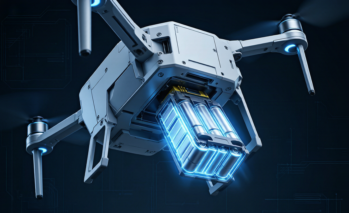
The architecture I specify uses a guided-insertion dock: two molded rails catch the pack and pull it into alignment, a spring-loaded latch provides a positive click at full seat, and a mechanical key enforces polarization so a tired operator at 6 a.m. cannot insert the pack reversed. A hard mechanical stop prevents a half-seated mate — the number-one cause of intermittent high-resistance contacts I see in field returns. The release is a single thumb latch that drops the pack clear in under a second for the 8–12 swaps per day the depot expects.
Strain relief on the internal harness is anchored within 30 mm of the connector so vibration fatigue concentrates in a replaceable boot, not in a soldered cell tab. In one teardown I measured a fatigued joint climb from 0.3 mΩ to 2.5 mΩ — that is 25 W of heat inside a housing rated for 5 W. The dock design is what keeps that joint from ever seeing the bending moment.
Connector and Electrical Interface for Rapid Swap
The swap connector carries the full flight current — often 100–160 A peak during the 6–9C takeoff spike — so its resistance budget is unforgiving. I size the interconnect to stay under 15% of the pack’s own DCIR, which on an 8–12 mΩ 6S 22 Ah pack means a connector plus lead resistance budget of about 1.2–1.8 mΩ. That points to an AS150 or XT150 family part on 8 AWG silicone, gold-over-nickel plating rated for 500–1000 mating cycles.
For anything at or above 8S (over 50 V) I mandate a pre-charge or anti-spark contact: the inrush into an empty bus capacitor can exceed 500 A and weld a cheap contact shut on the first swap. A 400–2000 µF pre-charge bank with a 10–100 Ω leading resistor solves it. The connector’s mechanical key (above) doubles as the electrical polarization guarantee, so we never rely on the operator reading a label.
Mounting, Vibration Isolation and Resonance Avoidance
Delivery drones land hard and often. The pack must survive landing acceleration as well as continuous rotor vibration. I qualify every delivery pack to DO-160 and MIL-STD-810 random-vibration profiles across 5–2000 Hz, using isolated elastomer mounts that decouple the cell stack from the airframe.
The subtle part is resonance. Rotor passage and blade-pass frequencies sit in a predictable band, and if the pack’s first structural mode lands there it will shake itself apart in weeks. We tune the mount stiffness so the pack’s mounted resonance clears the rotor/blade-pass band by at least 30%, verified on a shaker table before the design is frozen. A pack that hums at blade-pass frequency is a pack that loosens its own retention.
Sealing and Environmental Protection in the Parcel Bay
The cargo bay is a hostile place for a lithium battery. Parcel dust, road grit, rain during curb-side drops, and condensation from cold-chain boxes all want inside the pack. I specify IP5X–IP6X ingress protection for the bay-facing surfaces, a conformal coating on the PCB, and potted interconnects. Terminals are 316L stainless or nickel to resist the corrosion that kills a pack in a coastal or winter-salt environment, and a desiccant sachet holds the internal RH down over the pack’s service life.
No cooling fan. A fan is a dust ingress path and a single point of failure; in a sealed composite fuselage we move heat by conduction, not convection, which is the next section’s problem.
Thermal Path in a Sealed, Swap-Ready Bay
A delivery pack dissipates 10–30 W in a hover-duty cycle, and in a sealed composite fuselage that heat has nowhere to go by airflow. The design moves it by conduction: a thermal pad couples the cell stack to an aluminum tray that is itself bolted to the airframe’s structural skin, turning the whole lower fuselage into a heat sink. I place the temperature sensor at the hottest predicted cell, not at the BMS, because a pack that reads 32 °C at the board can be running 41 °C at a hot cell.
The service window I design to is 15–45 °C discharge and a 40 °C charge gate. Below about 10 °C lithium cells lose 15–30% of usable capacity, so for cold-climate depots I embed a 5–15 W pad heater that brings the core to a 10–25 °C window before the first sortie — far cheaper than oversizing the pack by 30–45%.
Cell Format Choice for a Delivery Pack
For a removable, swap-heavy delivery pack the cell format is a structural decision. Pouch cells pack the densest energy but swell 5–8% over life, so the dock must allow a designed swelling clearance and we retire any cell showing more than 5% puff. Cylindrical 21700 cells are self-supporting and far more vibration-tolerant, at a small energy penalty, which is why many high-cycle delivery fleets prefer them despite the marginal Wh/kg loss.
Chemistry follows the duty. For an energy-limited 0.5–1.5C hover duty, NMC or NCA at 200–250 Wh/kg and 500–1000 cycles is the default; high-power LiPo is rejected for delivery because its 20–30% energy penalty costs range we cannot spare; LFP at 120–160 Wh/kg is reserved for ground carts and buffer banks, not the airframe; and semi-solid at 250–300 Wh/kg is qualifying where mass and range genuinely pay a premium.
Regulatory Envelope — 100–160 Wh Packs and Transport
Every removable delivery pack I design respects the 100–160 Wh per-pack ceiling under FAA Part 107 and EASA SORA, because that is the threshold at which air-carrier and operational rules change. A pack at 159 Wh is a different compliance animal from one at 165 Wh, and I keep margin below the line on purpose.
For transport between depots, IATA rules require packs shipped at or below 30% state of charge, so the pack’s shipping mode and the dock’s storage mode both hold cells at 3.80–3.85 V/cell. The full build carries UN38.3 T.1–T.8 passage and IEC 62133-2:2017 documentation; I will not release a delivery pack to a fleet without both in the folder.
The Four-Number Custom Spec We Hand to Airframers
To turn a vague “make us a delivery battery” into a flight-ready pack, I compress the requirement into four numbers and hand them to the airframe team as the contract for a custom battery solution:
- Heaviest approved parcel mass — sets the CG window and the swell clearance.
- Longest leg distance or time — sets installed watt-hours after the 25–30% regulatory reserve.
- Swap cadence per shift — sets connector mating-cycle rating and latch durability.
- Available dock envelope — sets cell format, cooling path, and retention scheme.
Hand me those four numbers and a custom drone battery comes back that seats in under 60 seconds, survives the landing, and keeps the CG honest. That is the whole point of a purpose-built drone lithium battery for delivery: it is an airframe component first and a chemistry second.
Frequently Asked Questions
How fast can a delivery drone battery really be swapped?
With a guided-insertion dock and a single thumb latch, a trained operator completes a swap in under 60 seconds. The design target for an 8–12 swap per day depot is sub-60-second seating plus a positive mechanical click, so the bottleneck is the parcel, not the pack.
Why not just use a bigger battery instead of swapping?
Because a bigger pack raises AUW, shrinks parcel capacity, and pushes CG out of window. Hot-swap keeps the airframe light and the parcel bay useful; for an 80-drop day the energy throughput is 30–40 kWh per aircraft, which no single pack should carry.
What kills a delivery pack fastest in the field?
Mechanical faults: half-seated connectors, loose retention from resonance, and fatigued strain-relief joints. I see electrical aging last longer than poor docking mechanics, which is why the dock design gets more review time than the cells.
Do delivery packs need to be under 160 Wh?
For FAA Part 107 and EASA SORA operations, keeping each removable pack at or below 100–160 Wh avoids the stricter air-carrier and operational rules that trigger above that line. I design with deliberate margin under it.
Can the same pack work in a cargo drone and a ground cart?
Not ideally. The airframe pack is vibration-, weight-, and swap-optimized; a ground charging buffer is better served by LFP at 120–160 Wh/kg with 2000–4000 cycles. Mixing the roles costs you range or life.





