Drone Battery Integration for Delivery Drones
Why Delivery Integration Is a Fleet Problem, Not a Wiring Problem
When engineers ask me about drone battery integration delivery drones, they usually mean the harness — which gauge wire, which connector, how to bolt the pack into the fuselage. That framing works for a survey aircraft flown by a trained pilot who carries a multimeter. It fails completely for a delivery fleet turning 80 sorties a day per airframe, where no engineer ever touches the pack between flights. In that world, integration means something bigger: the battery has to behave as a self-describing, plug-and-play node in an automated ecosystem of swap stations, fleet software, and redundant power buses.
I have spent the last decade building the drone lithium battery and lithium battery packs that power these fleets, and the lesson is consistent. The chemistry and the cell grade are solved problems. What breaks a delivery program is the interface — the electrical, digital, and regulatory handshake that lets a depot swap a drone battery in under 30 seconds and trust that it will fly. A well-integrated custom drone battery is invisible to the operation; a poorly integrated one becomes a daily support ticket. This article walks through how we engineer that handshake, drawing on the UN38.3, IEC 62133-2:2017, FAA Part 107, EASA SORA, and IATA regimes that govern every connection.
Designing the Pack as a Plug-and-Play Fleet Node
The first integration decision is the connector. For delivery we standardize on AS150 or XT150 mates with 8 AWG gold-over-nickel conductors rated for 500–1000 mate cycles. Gold-over-nickel keeps the contact resistance at 0.25 mΩ when new and retires the part at 2.5 mΩ after the full cycle life — a 10× climb that still only dissipates ~25 W in a 5 W housing budget because the cross-section is generous. The pack’s DCIR sits below 10 mΩ measured at 1 kHz, and under a 3C/10 s pulse the bus voltage sag stays under 8%, with the interconnect contributing less than 15% of total pack resistance (≈1.5–1.8 mΩ across the main joint).
Every connector carries a pre-charge circuit for packs above 8S or 50 V: a 400–2000 µF reservoir in series with a 10–100 Ω resistor that bleeds the inrush before the main contactor closes. In a manual swap this is a two-step button. In an automated depot it is a handshake the robotics controller drives — the station verifies pre-charge completion before it latches the main bus, so a cold or faulty pack never sees a 200 A inrush arc.
Redundant Power Architecture for Larger Delivery Airframes
Small delivery quadcopters run a single pack. Medium and large airframes — the ones carrying 3–5 kg parcels over 15–25 km — increasingly use two parallel packs with ideal-diode OR-ing. The benefit is failover, not capacity. If one pack’s BMS trips on a cell fault, the ideal diode isolates it in microseconds and the remaining pack carries the return-to-launch (RTL) profile alone. We size the single-pack RTL margin at 25–30% of usable capacity, matching the FAA Part 107 and EASA SORA reserve requirement, so a single-string failure never becomes a dropped parcel or a forced landing.
The integration subtlety is current sharing. Two packs with a 5% DCIR delta will split load unevenly, and over a day of sorties one ages faster. We bin packs at incoming inspection to ±5% DCIR and tag each with a QR serial, so the fleet software can pair like-binned packs onto the same airframe and equalize wear across the depot.
Co-Integrating the Payload and Release Mechanism
A delivery drone draws from one pack for everything: propulsion, the onboard computer, the RTK module, and the cargo release servo. The release servo is the most dangerous load on the bus because it fires at the worst moment — the end of the mission, when the pack is at its lowest state of charge and highest internal resistance. If the release starves, the parcel never drops and the aircraft returns heavy.
We solve this with power sequencing and a regulated payload rail. The release actuator sits on a dedicated, isolated DC-DC converter with a 20–40 ms holdup capacitor, so a transient sag on the main bus cannot interrupt the drop command. The cargo bay door, the lift mechanism, and the onboard computer each get their own regulated sub-rail with independent current limiting. The same architecture we use to protect RTK lock on mapping aircraft — an isolated sensor rail that rides through bus transients — here protects the single most revenue-critical action of the whole flight.
Telemetry Integration: BMS to Fleet Operations
A delivery battery is a data source, not just an energy source. Our BMS broadcasts on CAN / UAVCAN at 1 Mbps, pushing per-cell voltage, pack current, temperature array, and state of charge at 1–10 Hz with a 100 Hz fault event channel. In a manual operation that telemetry is for the pilot. In a delivery fleet it feeds the dispatch software directly.
Concretely, the fleet ops console reads each pack’s state-of-health telemetry between sorties and decides routing: a pack at 82% SOH is assigned short urban loops, a fresh pack gets the 25 km cross-town run. A pack that logged a single over-temperature event during a sortie is automatically pulled from the rotation and flagged for bench inspection. This closed loop is what lets a homogeneous fleet of 200 packs sustain predictable uptime without a battery engineer on every shift. It also enforces configuration consistency — BMS firmware and fuel-gauge models are version-locked and pushed over-the-air, so no airframe quietly flies an older calibration than its siblings.
Automated Swap-Station Electrical Integration
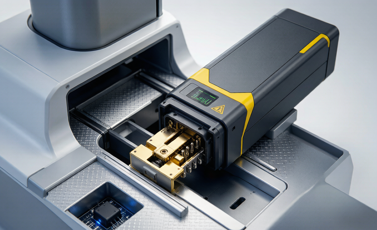
The swap station is where integration meets automation. The dock presents pogo-pin or blade contacts that align with the pack’s gold-over-nickel interface; a robotics arm seats the pack, the station runs the pre-charge handshake, then closes the main contractor and begins a 1C–2C charge at a temperature-gated 40°C ceiling. We add contact cleaning — a brief wipe cycle every N mates — because pogo-pin resistance drift is the leading cause of swap faults in dusty depot environments.
Critically, the station enforces transport-state discipline. Per IATA PI 965/968, every lithium battery staged for any road or air movement leaves the depot at or below 30% state of charge. The swap station does not just charge; it can also deliberately hold a pack at 30% for onward logistics, and it logs that state into the same serial record the BMS and fleet software share. One source of truth, three systems reading it.
Bench Integration Test Before Fleet Entry
No pack enters the fleet on paper compliance alone. Before a new pack design or a new bin cohort flies a paid delivery, we run a bench integration test that replays a full mission profile on a load bank: takeoff spike, cruise, hover-drop, and RTL, with the 25–30% reserve margin enforced. We confirm bus sag stays under 8%, that the CAN telemetry the fleet software received exactly matches what the BMS computed (no dropped or stale nodes), and that 200 consecutive hot-swap pre-charge cycles complete without a contactor fault. If a pack passes this, the swap station and the fleet console already know how to treat it — because they were part of the same test.
This is also where we re-verify the transport and safety envelope: UN38.3 T.1–T.8 and IEC 62133-2:2017 compliance for the cell build, IATA 30% SoC staging, and the 100–160 Wh cell-level ceiling that keeps each pack inside the FAA Part 107 and EASA SORA carry rules. Integration is only real if every layer of the stack agrees on the same numbers.
Transport and Regulatory Integration
The final integration layer is regulatory, and for delivery it is more demanding than for a manually operated aircraft because packs move constantly — between depots, in vans, occasionally on feeder aircraft. We engineer the pack so that compliance is a property of the physical design, not a paperwork exercise. Cells are graded to ±2% capacity and ±5% DCIR at incoming inspection, built into an encapsulation rated IP5X–IP6X with no fan, and serialized so any transport incident can be traced to a cell lot and a BMS firmware version.
Chemistry choice follows duty: NMC/NCA at 200–250 Wh/kg with 500–1000 cycles for the main delivery fleet where energy density pays for range, LFP at 120–160 Wh/kg with 2000–4000 cycles for ground-buffer and high-cycle depot roles. A custom battery solution for a specific airframe pairs the right chemistry with the right connector bin and the right firmware, so the drone lithium battery that arrives at the depot is already the pack the swap station expects. When a customer needs a different envelope — a heavier parcel, a colder route, a tighter airframe — we design a custom drone battery rather than force a standard pack to do a job it was not integrated for. That is the difference between a drone battery that survives 80 sorties a day and one that quietly degrades after two weeks on the dock.
Frequently Asked Questions
What connector do you use for automated delivery drone battery swaps?
We standardize on AS150 or XT150 mates with 8 AWG gold-over-nickel conductors rated for 500–1000 cycles, keeping contact resistance between 0.25 mΩ new and 2.5 mΩ retired. Each connector carries a pre-charge circuit for packs above 8S or 50 V, and in an automated depot the swap station drives that pre-charge handshake before latching the main bus.
How do you keep a delivery drone flying if one battery pack fails mid-flight?
Larger airframes use two parallel packs with ideal-diode OR-ing. If one BMS trips, the ideal diode isolates it in microseconds and the surviving pack carries the return-to-launch profile alone, sized with a 25–30% FAA Part 107 / EASA SORA reserve so the aircraft always makes it home with the parcel.
Why does the cargo release need its own power rail?
The release servo fires at the end of the mission when the pack is at its lowest charge and highest resistance — the worst bus condition. We put it on an isolated DC-DC converter with a 20–40 ms holdup capacitor so a transient sag cannot interrupt the drop command, protecting the single most revenue-critical action of the flight.
How does the battery talk to delivery fleet software?
The BMS broadcasts on CAN / UAVCAN at 1 Mbps — per-cell voltage, current, temperature, and state of charge at 1–10 Hz with a 100 Hz fault channel. Fleet ops reads state-of-health between sorties to assign routes and pull faulty packs, and version-locks firmware so every airframe flies the same calibration.
What transport rules apply to delivery drone batteries moving between depots?
Packs staged for road or air movement leave at or below 30% state of charge per IATA PI 965/968, built on cells compliant with UN38.3 T.1–T.8 and IEC 62133-2:2017, with each pack serialized so any incident traces to a cell lot and firmware version. The swap station both charges and deliberately holds packs at 30% for onward logistics.