
Drone Battery Integration for Inspection UAVs
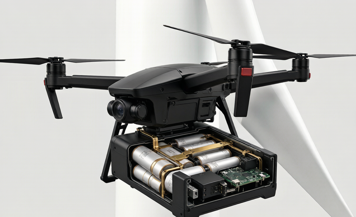
When a client asks me to engineer a drone battery for inspection work, the conversation almost never starts with cells. It starts with the asset they fly against — a wind-turbine blade, a transmission tower, a flare stack, a bridge truss, a live substation. I’m Karl Huang, Senior lithium battery Engineer at Horizon Power, and after a decade of putting lithium packs on airframes, I’ve learned that inspection integration is its own discipline. The pack isn’t a bracket you bolt on; it’s co-designed with the airframe, the payload, and the hostile electromagnetic environment those assets create. Get it wrong and your LiDAR drops lock three meters from a power line. Get it right and the battery becomes a true field-replaceable unit (FRU) that a technician swaps in under a minute with gloved hands, in the field, with no bench.
Why Inspection Integration Is a Different Problem
Most consumer and cinema drones treat the battery as a sealed black box snapped into a tray. Inspection UAVs can’t afford that luxury. An inspection drone lithium battery lives in a world of long loiter corridors, sensor suites drawing steady regulated power, and surfaces that emit RF, corona, or heat. The integration challenge is three-fold: the pack must fit a specific airframe bay, it must feed a clean isolated rail to the payload, and it must not become a noise source or a hazard when the aircraft hovers a few meters from a 110 kV busbar.
That is why we treat integration as co-engineering, not assembly. At Horizon Power a custom battery solution for inspection always begins with the airframe geometry and the payload bill of materials, never with a catalog cell. The lithium battery chemistry, the mechanical envelope, and the sensor-power architecture are chosen together so the finished pack behaves as a single component rather than a stack of afterthoughts.
- The airframe sets the envelope and the center-of-gravity (CG) window.
- The payload sets the isolated rail’s voltage, current, and noise floor.
- The inspected asset sets the shielding and sealing budget.
Conformal, Airframe-Specific Mounting and the CG Window
Inspection airframes are heterogeneous: a close-in quad for tower work, a VTOL for corridor surveys, a tethered or hybrid airframe for long loiter. Each has a different bay, so a custom drone battery is molded or machined to the specific airframe rather than adapted from a generic brick. The pack typically sits in the lower third, centered, holding CG at 25–35 percent of all-up weight (AUW) within ±15 mm across every load case — empty, nominal, and with the heaviest approved payload plus gimbal, LiDAR, and any gas or optical sensor.
A CG error is expensive and chemistry-blind. If the pack sits too far forward or aft, the flight controller holds constant-thrust trim to counter the moment, burning 8–12 percent of endurance that no better cell chemistry can recover. We verify the CG window on a balance jig during first article inspection, not after the first flight.
Mounting also has to survive the inspection environment. We keep strain relief anchored within 30 mm of the connector so vibration doesn’t fatigue the joint — a fatigued joint climbs from 0.3 mΩ to 2.5 mΩ, which is 25 W of heat inside a 5 W housing. Retention must survive landing g yet release in under 60 seconds for field swaps. A mechanical hard stop prevents a reversed or half-seated mate, which would otherwise short the busbar on insertion.
Co-Integrating the Isolated Sensor Power Rail
This is where inspection integration diverges most sharply from a generic build. The pack physically houses the isolated regulated sensor power module, and we co-locate the DC-DC stage with the cell stack to keep the noisy 100+ A propulsion wiring as short as possible. The isolated rail feeds the payload at 24 V for LiDAR, 12 V for the gimbal, and 5 V for the companion computer, with a 20–40 ms holdup so a propulsion sag never blinks the sensors.
The resistance budget is the same one we apply across the Horizon Power inspection family: pack DCIR under 10 mΩ measured at 1 kHz, sag below 8 percent on a 3C / 10-second pulse, and interconnect resistance below 15 percent of total pack resistance — which means the connector and busbar together stay at 1.5–1.8 mΩ. We reach that with AS150 or XT150 connectors on 8 AWG cable with gold-over-nickel plating rated for 500–1000 mates. Above 8S or 50 V we add a pre-charge stage of 400–2000 µF plus a 10–100 Ω resistor on the leading contact to kill the inrush that would otherwise arc the connector.
Common-mode filtering on the isolated rail is tuned to the specific payload’s noise floor. A thermal camera and a LiDAR don’t forgive the same ripple, so the filter is part of the custom spec, not a generic add-on. The result is a sensor rail that stays regulated even when the propulsion bus sags during a hard yaw turn next to a steel tower.
Designing the Pack as a Field-Replaceable Unit
For inspection programs the battery has to be an FRU. A field technician on a wind farm or a substation yard should not need a bench, a laptop, or a torque sequence. The pack uses a mechanical polarization key so it can only seat one way, a tool-free spring latch, and a blind-mate or pogo connector that self-aligns even with gloved hands. A swap takes under 60 seconds.
We rate the connector for 500–1000 mates and retire it on resistance drift rather than a calendar date. Because the pack is a sealed FRU, the technician carries two or three spares in a case and keeps flying — no on-site balancing, no firmware flashing. That field-swappability is exactly what a custom drone battery program buys you over a repurposed hobby pack.
Field handling follows a simple protocol: FIFO by serial, charge gated at 40°C, storage at 3.80–3.85 V/cell, and transport at or below 30 percent state of charge per IATA. We retire a pack at 80 percent state of health, twice its initial internal resistance, a 50 mV cell delta, or 5 percent puff — whichever comes first.
Shielding the Pack Against the Asset It Inspects
Inspection means flying close to the thing you’re inspecting, and that thing is often a strong emitter or a conductive structure. We treat the pack casing as a shield element, not just a container. Shielded inductors, spread-spectrum DC-DC switching, and a co-located ground plane keep the converter off the RF front-end, so the aircraft keeps RTK lock and the LiDAR keeps its point cloud when the drone is three meters from a transmission line.
Sealing is matched to the duty: IP67 for offshore and salt-fog turbine work, with conformal coating, potting, 316L stainless hardware, and a desiccant pack — no fans, because a fan is an ingress path and a failure point. Thermal management is by conduction, not convection: a thermal pad transfers heat to an aluminum tray bolted to the skin, and the temperature sensor sits at the hottest predicted cell, not on the BMS board.
Vibration is cleared by shaker test to DO-160 and MIL-STD-810 across 5–2000 Hz, with the mounted resonance kept more than 30 percent above the rotor and blade-pass bands. A pack that rings at the blade-pass frequency loosens its own fasteners, so we verify the margin before the aircraft ever arms.
Verifying Integration Before the Aircraft Arms
Integration isn’t done when the pack clicks in. We run a bench harness test that replays the inspection mission profile — climb, cruise, sensor-spike draws for the gimbal (20–80 W), thermal (20–45 W), LiDAR (15–40 W), gas or optical (5–20 W), companion computer (10–25 W), RTK (5–12 W), and lights (5–20 W) — and confirm sag stays under 8 percent and that the CAN or UAVCAN telemetry from the BMS matches the bench instruments.
On the aircraft we run a field integration check: the flight controller enumerates the pack over the bus, confirms isolated-rail regulation, and only then arms. A 12S 22 Ah NMC pack typically gives about 28 minutes of loiter with a 25–30 percent reserve held for the FAA Part 107 or EASA SORA margin and return-to-launch. We also cold-start at −20°C with the 5–15 W pad heater active, because inspection happens in winter turbine yards where capacity fades from 100 percent at 25°C to about 85 percent at 0°C, 70 percent at −10°C, and 55–60 percent at −20°C; the heater recovers roughly a third of that loss between 10°C and 25°C.
Compliance You Build In, Not Bolt On
Every inspection pack leaves the line already qualified, not qualified after the fact. We design to UN38.3 tests T.1 through T.8, IEC 62133-2:2017, and IATA PI 965/968 with transport at 30 percent state of charge. Flight is bounded by the 100–160 Wh per-pack ceiling under FAA Part 107 and EASA SORA, with the 25–30 percent reserve baked into the usable-energy budget rather than left to the pilot.
Chemistry selection follows the duty: NMC or NCA at 200–250 Wh/kg with 500–1000 cycles is the default for airframe mass budget; LFP at 120–160 Wh/kg with 2000–4000 cycles is reserved for ground carts and buffers; semi-solid at 250–300 Wh/kg is qualifying where mass or endurance pays a premium. We reject high-power LiPo for inspection because its 20–30 percent energy penalty hurts more than its burst helps.
Frequently Asked Questions
What does “drone battery integration” actually mean for inspection UAVs?
It means co-engineering the lithium pack with the airframe, the payload, and the inspected asset’s environment so the battery, the CG, and the isolated sensor rail behave as one component. Integration covers conformal mounting, sensor-rail co-location, field-replaceable design, shielding, and verified bench-to-aircraft testing.
Why is the sensor power rail isolated inside the pack?
Inspection payloads like LiDAR and thermal cameras need clean, regulated power and a 20–40 ms holdup so a propulsion sag never corrupts data. Housing the isolated DC-DC stage in the pack and keeping propulsion wiring short protects the payload’s noise floor when the aircraft is close to emitters.
How long does a field swap take, and what does the technician need?
Under 60 seconds with gloved hands and no tools, using a polarized key and blind-mate connector. The technician carries two or three spare FRU packs; there is no on-site balancing or firmware work.
How cold can an inspection drone battery operate?
With the pad heater active between 10°C and 25°C, a pack holds useful capacity down to about −20°C, where it retains 55–60 percent of its 25°C capacity. The heater recovers roughly a third of that cold loss.
Which standards apply to these packs?
UN38.3 (T.1–T.8), IEC 62133-2:2017, IATA PI 965/968 at 30 percent SoC for transport, and the 100–160 Wh per-pack flight ceiling under FAA Part 107 and EASA SORA with a 25–30 percent reserve.





