
Drone Battery Performance for Racing Drones: Taming
As a senior lithium battery engineer at Horizon Power, I have watched more race weekends turn on a connector than on a cell. Pilots obsess over the C-rating and the watt-hour number printed on the shrink wrap, then lose a finals gate because three milliohms of resistance lived quietly between the pack and the ESC. In this piece I want to walk you through the part of drone battery performance racing drones teams almost never measure: the external power path — busbar, connector, and harness — and why those last meters decide whether your pack’s headline numbers ever actually reach the prop.
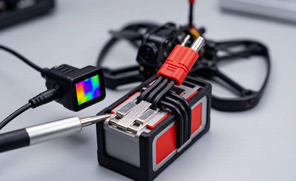
The Performance You Spec Is Not the Performance You Fly
A 6S 1300 mAh 45C pack’s spec sheet promises roughly 58 Wh and a burst current that looks enormous on paper. But the cell is only half the story. The propeller sees the voltage at the ESC input, not at the cell terminal. Every weld, every busbar joint, every centimeter of wire adds series resistance. At the 100–200 A current a modern FPV rig pulls, even 10 mΩ costs you real volts. The cells can deliver 25.2 V fresh off the charger; the prop may see 23 V. That two-volt gap is performance you paid for and quietly threw away. When I tune a drone battery for a customer’s race class, I treat the external path as a first-class design parameter, not an afterthought.
Mapping the External Power Path, Milliohm by Milliohm
Let me lay out the chain from cell tab to ESC, because each link has a measurable cost:
- Cell-to-busbar weld. The first joint. A good laser or ultrasonic weld lands around 0.15 mΩ per joint, but a cold or oxidized spot weld can be ten times that.
- Busbar. Nickel strip (the stuff you spot-weld to 18650/21700 tabs) is convenient but resistive. A 0.15 mm × 8 mm nickel bridge across a 6S string typically runs 5–9 mΩ. Copper or copper-plated busbars cut that by 4×.
- Pack-to-harness connector. The usual suspect. An XT60 pair reads 4–6 mΩ; a worn one climbs fast.
- Silicone harness. 12 AWG over 10 cm is about 0.5 mΩ; 14 AWG doubles that.
- Harness-to-ESC connector. Same family of loss as the pack connector.
Add it up and the external path on a typical drone lithium battery for racing lands at 15–25 mΩ — while a healthy cell group’s internal DCIR is only 8–12 mΩ. In other words, the wiring can be 30–50% of your total pack resistance, and almost none of it shows up on the label.
There is a second, nastier effect: this loss compounds as the pack sags. Cell voltage falls under load, so the percentage eaten by the external path grows through a run. A pack at 25.2 V fresh loses ~9% to a 19 mΩ path; at 21.0 V near the end of a heat the same 2.28 V drop is ~11% — and because thrust follows V², that late-race sag bites hardest exactly when you are fighting for the last gate. I have seen packs that felt punchy on the first lap fade badly on lap four for no cell reason at all, purely because the connector was cooking.
Putting Real Numbers on the Last-Meter Voltage Drop
Numbers make the point better than warnings. Take a 6S 1300 mAh 45C racing pack with a 120 A race-average punch. Give the external path a conservative 19 mΩ (busbar 6, XT60 9, harness 4).
- Voltage drop = I × R = 120 A × 0.019 Ω = 2.28 V.
- Pack terminal 25.2 V → ESC sees 22.9 V.
- Heat dumped into wires/connector = I²R = 120² × 0.019 = 273 W of pure loss heating your airframe, not making thrust.
- Thrust scales roughly with V² at the motor: (22.9 / 25.2)² = 0.826 → about 17% less thrust than the spec sheet implies.
Now move to an EC5 connector (1.5 mΩ) plus 10 AWG harness plus a copper busbar (3 mΩ): external path 8.5 mΩ → drop 1.02 V → ESC sees 24.2 V → (24.2 / 25.2)² = 0.922 → only ~8% loss. You just recovered roughly 9% of thrust by fixing the wiring, not the cells. At a finals gate, that is the difference between making the gap and clipping a pole. That is the whole game of drone battery performance racing drones engineering.
Connectors: XT60, XT90, EC5, and the Direct-Weld Option
Connectors are where I see the most avoidable losses. My field guidance:
- XT60. Cheap and ubiquitous, rated around 60 A continuous. Contact resistance climbs with every mate cycle, and at 120 A it runs hot. Fine for sport flying; risky for finals.
- XT90. Same geometry, thicker pins, ~90 A, lower contact resistance. A reasonable step up.
- EC5. Bullet connectors with large contact surface, typically 1.5–2.5 mΩ per pair, and they handle 120 A without significant heating. This is my default for anything above 100 A.
- Direct-weld / soldered pigtail. Removes the connector entirely (0 mΩ) but kills serviceability and turns a crash repair into a short-circuit hazard. I only use it on closed custom packs where the customer accepts the trade-off.
Rule I enforce on every lithium battery we build for racing: above 80 A sustained, run EC5 or direct-weld. Never trust a worn XT60. I 4-wire measure contact resistance on incoming connector lots and reject any reading above 3 mΩ.
Busbar and Harness Design Rules That Protect Performance
A few rules I bake into every race pack:
- Busbar material. Nickel is fine for the spot-weld cell tabs, but a long 6S high-current bridge in pure nickel is a resistor. Use copper or copper-plated braid for the bridge.
- Cross-section. Keep current density below ~6 A/mm². At 150 A you need ~25 mm² equivalent — a 0.3 mm × 8 mm copper strip is only 2.4 mm², so stack or braid it.
- Harness length. 10–12 AWG silicone, as short as the frame allows. Every extra 10 cm of 12 AWG at 120 A adds ~0.5 mΩ and ~7 W of heat.
- Crimp, don’t solder. A crimped ferrule beats a soldered joint for vibration life — solder wicks into the strands and cracks. Cold solder joints are the number-one intermittent IR fault I find in returned packs.
- Thermal budget. P = I²R; 273 W in a connector is a fire risk. Size so the sustained temp rise stays under 25 °C at race current, verified with an IR camera.
These details are exactly what separate a generic pack from a proper custom battery solution — we spec the full power path, not just the cell.
Proving the Path on the Bench and at the Track
None of this is theory; it is measurable, and I gate every shipment on it:
- 4-wire Kelvin milliohm meter. Measure busbar-to-busbar and connector-to-connector resistance, not just the cell. A pack can have perfect cells and a 20 mΩ external path.
- Thermal camera at 120 A. Watch the connector and busbar during a discharge. Any hot spot above 60 °C at race current means a redesign.
- Lap correlation. Log ESC input voltage (not pack voltage) at 100 Hz and compare to lap time. A pack that holds 24 V at the ESC versus 22.5 V typically correlates to 0.2–0.5 s per lap on a tight track — a lifetime in finals.
- Acceptance gate. External path resistance ≤ 10 mΩ at the 6S level for any pack we ship as a racing drone lithium battery; we reject the lot above 12 mΩ. Every pack is serialized so a field IR fault traces back to its build record.
Compliance is unchanged from the rest of our line: UN 38.3 (T.1–T.8) transportation testing, IEC 62133-2 cell safety, and the FAA/EASA 100 Wh air-transport band. A clean power path does not get you out of the safety case — it just makes sure the performance you qualified is the performance you fly.
The discipline pays off across a season. When we started gating on external-path resistance, mid-event voltage cutouts from “mystery” sag dropped sharply, and the packs that came back for teardown showed clean, cool connectors instead of the discolored XT60s we used to see. It is a small, unglamorous measurement — a milliohm meter and an IR camera — but it is the difference between a drone battery that performs on paper and one that performs on the clock. If you want the same result without building the test rig yourself, that is exactly the kind of detail we fold into a custom battery solution: we specify and verify the entire power path, serialize each pack, and hand you the measured resistance budget alongside the watt-hour number.
Frequently Asked Questions
Does connector resistance really matter at racing currents?
Yes. At 100–200 A, every milliohm is a volt and watts of heat. A 9 mΩ connector at 120 A drops 1.08 V and wastes 130 W. That is thrust and endurance you never see at the prop.
XT60 vs EC5 — which should I run?
For sport flying under 60 A, XT60 is adequate. Above 80–100 A sustained, move to EC5 or direct-weld. The EC5’s larger contact area keeps resistance and heating roughly 2–3× lower under race loads.
How much harness length is too much?
Keep it as short as the frame permits. Each 10 cm of 12 AWG at 120 A adds about 0.5 mΩ and 7 W of heat. Route the pack close to the ESC; don’t let the wiring become the bottleneck in your drone battery performance racing drones build.
Can I just solder the pack directly to the ESC?
You can, and it removes connector loss entirely, but you lose serviceability and create a short-circuit hazard during repair. I reserve direct-weld for closed custom packs where the customer accepts that trade-off and we handle the build.
How do I measure my pack’s external resistance?
Use a 4-wire Kelvin milliohm meter across the pack terminals and again across each connector and busbar. Subtract the cell-group DCIR (from the spec) to isolate the external path. Anything above ~12 mΩ on a 6S race pack is worth redesigning.





