Semi-Solid State Battery Design for EV Packs
Why Semi-Solid Changes the EV Pack Design Envelope
When I first started specifying lithium-ion packs for electric vehicles a decade ago, the pack was treated as a fire risk to be contained. Every design decision — module housings, thick ceramic barriers, oversized vent channels, generous thermal margins — was driven by the flammability of a liquid organic electrolyte. semi-solid state battery chemistry flips that assumption. A semi-solid cell replaces most of the flammable solvent with a quasi-solid gel electrolyte, and in our tear-downs the thermal-runaway onset temperature climbs roughly +30 to +50°C above a comparable NMC lithium-ion cell. That single shift is what makes a genuinely different semi-solid state battery design for EV packs possible, not just a re-labeled Li-ion pack.
The practical consequence is that the design envelope widens on three axes at once: you can trade away module-level structure, you can shrink the gas-management volume, and you can tighten the cell-to-cell spacing. But you cannot simply delete the safety hardware and call it lighter. The job of a pack design engineer is to reinvest those freed grams and millimeters into durability, servicability, and certification headroom. In this article I walk through the architecture decisions my team makes when we move a solid-state battery cell from a datasheet into a road-legal EV pack, and why we tune each custom battery solution around the cell’s actual abuse behavior rather than its marketing sheet.
Cell Format Selection: Why Prismatic Leads for Semi-Solid CTP
The first fork in any custom battery solution is the cell format. For a semi-solid EV pack, the choice is almost always between large-format prismatic cells and pouches; cylindrical 21700-class cells are rarely the right answer because their cylindrical geometry wastes pack volume that a pouch or prismatic cell recovers.
- Prismatic (favored): A 100–120 Ah prismatic semi-solid cell reaches 300–360 Wh/kg at cell level and, more importantly, presents large flat faces that are easy to cool, compress, and bond. Flat faces let us skip module cans entirely and glue the cells straight into the pack tray — the cell-to-pack (CTP) approach.
- Pouch (niche): Pouch gives the best volumetric density but demands an external compression fixture and is unforgiving on swell. For a fleet vehicle with an 8-year warranty, I reserve pouches for niche low-volume programs.
- Cylindrical (rarely): Only chosen when an existing 21700 line must be reused; the packing efficiency penalty (~15–20% versus prismatic CTP) usually erases the semi-solid energy-density advantage at pack level.
In our 90 kWh reference pack, moving from a cylindrical module architecture to large-format prismatic CTP cut the cell count from roughly 720 cells to about 96 cells. Fewer cells means fewer welds, fewer failure nodes, and a dramatically simpler manufacturing line — a point I return to when we discuss cost, but it starts as a design decision.
Cell-to-Pack Mechanical Integration and the Structural Load Path
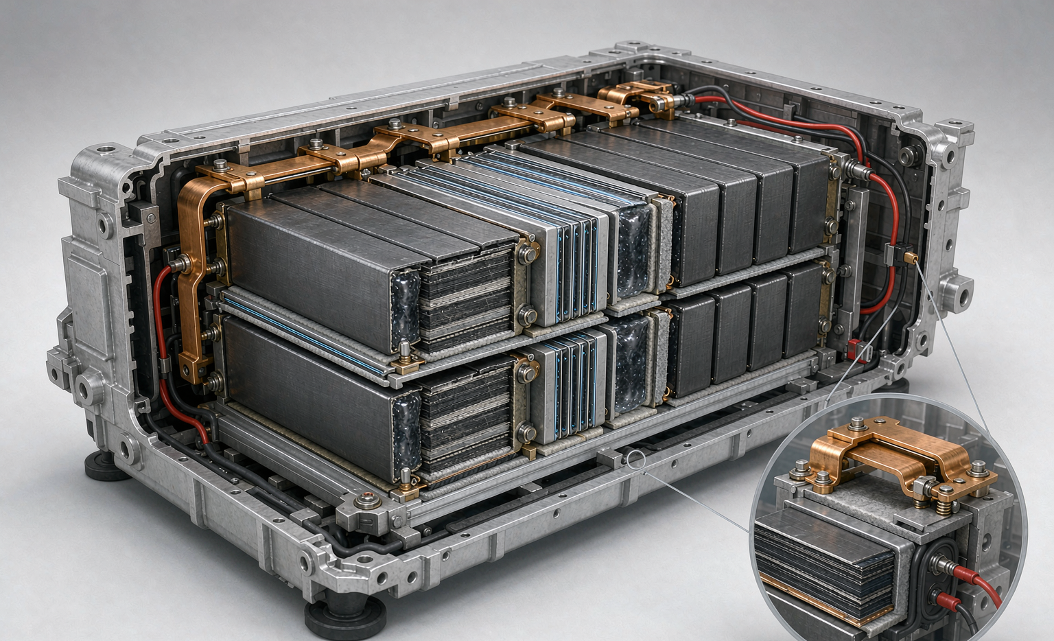
Once you accept that the module housing is dead weight, the cells themselves become part of the structure. In a semi-solid CTP pack the load path runs: cell stack → end plates → side beams → pack tray → vehicle body. We bond the prismatic cells to the tray and to one another with a two-part structural epoxy rated for the vehicle’s lifetime vibration spectrum (we validate against MIL-STD-810H class random vibration and the OEM’s road-profile duty cycle).
The higher thermal-runaway onset of semi-solid chemistry lets us narrow the cell-to-cell gap from the ~2 mm ceramic standoff we used in Li-ion to roughly 0.8–1.2 mm of a thin, compression-grade gap filler. That recovered ~6–9% pack volume. But I still keep a directional vent channel behind each cell row: a safer cell is not a non-venting cell, and the certification bodies do not care that your chemistry is “mostly” solid.
Thermal-Mechanical Co-Design: Cooling Plate, Busbar, and Compression
A quasi-solid gel electrolyte still swells on charge, so the pack must apply a constant compressive pre-load — typically 0.3–0.7 MPa — across the cell face for the life of the pack. The elegant trick is to let the liquid-cooling plate do double duty: it is both the heat exchanger and one compression member of the sandwich.
- Cooling plate: A brazed aluminum plate with serpentine channels runs along the cell’s large face, holding the stack at a 20–35°C window. We size it for a <4°C gradient across the pack under a 2C continuous load.
- Busbar routing: Laser-welded pure-nickel or nickel-plated copper busbars sit on the top edge, kept >3 mm clear of the cell wrapper with standoffs. We measure weld resistance with a 4-wire Kelvin method and reject any joint above 0.15 mΩ.
- Compression frame: A glass-fiber-reinforced end plate and a long-bolt pre-load system hold the target compression; a Belleville washer stack absorbs the slow swell so the busbars never see the strain.
This co-design is where semi-solid’s lower solvent mass pays a quiet dividend: less electrolyte to heat and less vent gas to manage means the cooling plate can be thinner, recovering more volume for active material.
Electrical Architecture and Protections for 400V and 800V
Most EV programs today are split between 400V (mainstream) and 800V (premium, faster charge). A semi-solid pack supports both because the cell voltage window is unchanged from NMC Li-ion; only the series count differs. Our reference 90 kWh pack is 108S1P for 400V and 216S1P for 800V.
Protection design is non-negotiable regardless of chemistry:
- Per-string fusing: A pyrotechnic disconnect (pyro-fuse) on the main bus opens the pack in <3 ms on a hard short.
- Isolation monitoring: A DC-isolation-resistance sensor trips below 500 Ω/V, satisfying the functional-safety floor for high-voltage contact.
- BMS topology: A slave board per cell-group measures voltage and temperature; a master BMU runs the contactor logic, balancing, and the CAN/SMBus telemetry the vehicle needs.
- Pre-charge: An in-rush-limiting resistor protects the contactors every time the pack connects to the inverter.
I treat the BMS as a safety device first and an energy optimizer second. A drone battery I designed years ago taught me that the linkers and thresholds you set at 4.25 V / 3.0 V cell limits are what actually keep an aircraft — or a car — out of trouble.
Venting, Gas Management, and Crash Intrusion
Even with a higher TR threshold, a semi-solid cell that does go into runaway will vent hot gas and eject material. The pack design must give that gas a planned exit. We route each cell row’s vent to a shared plenum that discharges downward and away from the cabin through a burst-disc panel, with a flame-arrestor mesh sized for the expected particle load.
The enclosure itself is IP67 sealed with a continuous gasket, hard-anodized 6061-T6 rails, and stainless hardware, and we surround the pack with a crash intrusion zone of 80–100 mm on the sides most exposed in a side-pole test (ECE R100). Ingress protection and corrosion resistance matter because an EV pack outlives the vehicle’s paint warranty — a lithium battery that survives the crash but rusts through its tray in year six is still a field failure.
Standards and the Validation Plan I Actually Run
A pack is not designed until it is certified. For a semi-solid EV pack bound for global sale, the validation matrix I build covers transport, cell safety, stationary/industrial use, and automotive:
- UN38.3 T.1–T.8 — the transport floor (altitude, thermal, vibration, shock, external short, impact, overcharge, forced discharge).
- IEC 62133-2 — secondary cell safety for portable/Li-ion cells.
- IEC 62619 — industrial battery safety (relevant for the pack-level abuse tests).
- GB 38031 — the Chinese EV traction-battery standard (thermal-spread resistance for 5 minutes).
- ECE R100 — UN regulation for electric power-train safety.
- UL 2580 — the North American EV battery standard.
- IATA Section II / FAA-EASA — air-transport handling for prototype and service cells.
The honest engineering note: certification is a floor, not a prediction of fleet reliability. We therefore add a burn-in and aging gate — every pack is cycled, re-graded, and DataMatrix-tagged so a field failure can be traced to a cell lot, a weld set, or a BMS firmware revision.
Frequently Asked Questions
Is a semi-solid state battery design just a safer lithium-ion pack?
Not quite. The quasi-solid electrolyte reduces flammable solvent mass and raises the thermal-runaway onset by roughly 30–50°C, which lets the pack designer remove module housings, shrink barriers, and tighten spacing. But the cells still need venting, cooling, isolation monitoring, and full certification — so the design discipline is the same, only the margins are better.
Why do you prefer prismatic cells for EV packs over cylindrical?
Large-format prismatic cells have flat faces that are easy to cool, compress, and bond directly into the tray. In a 90 kWh reference pack, prismatic CTP cut the cell count from about 720 to 96 versus a cylindrical module design, simplifying manufacturing and reducing failure nodes. Cylindrical only wins when an existing line must be reused.
How does cell-to-pack change the structural load path?
In CTP the cells become structural members. The load runs from the cell stack through end plates and side beams into the pack tray and then the vehicle body. A structural epoxy bonds the cells in place, and a directional vent plenum behind each row handles any off-nominal venting without pressurizing the enclosure.
Does semi-solid chemistry need a different BMS than lithium-ion?
The voltage window is essentially the same as NMC Li-ion, so the BMS topology (slave per group, master BMU, contactors, pre-charge) carries over. We keep the same 4.25 V / 3.0 V cell limits and add a 4-wire Kelvin weld check plus a DataMatrix genealogy so field failures are traceable.
What standards must a road-legal semi-solid EV pack meet?
At minimum UN38.3 T.1–T.8, IEC 62133-2, IEC 62619, GB 38031, ECE R100, UL 2580, and IATA Section II / FAA-EASA for transport. We treat these as the floor and add burn-in, aging gates, and lot-level genealogy for real fleet reliability.