Sodium-Ion Battery Integration for Street Lights: A Senior
I have spent the better part of the last two years moving sodium-ion battery packs out of the lab tray and into real municipal hardware, and solar street lighting is where the technology has surprised me most. Not because the chemistry is exotic — it is not — but because the integration problems are refreshingly different from the lithium ones I have solved for a decade. A grid-independent luminaire is one of the harshest duty cycles you can ask a sodium-ion battery to survive: it charges in bursts from a panel that is only occasionally clean, it discharges every single night without exception, and it does all of that inside a steel pole that reaches 65 °C in July and −25 °C in January.
What follows is the integration sequence I use with municipal engineers and OEM customers today. It is deliberately ordered: energy budget first, then electrical mapping, then charge control, then mechanics, then environment, then intelligence, then paperwork. Skipping step two is the single most common mistake I see, and it is the one that produces poles that go dark at 2 a.m. in their second winter.
What “Integration” Really Covers on a Solar Street Light
When a purchasing team asks me for a sodium-ion battery integration for street lights, they usually mean “supply a pack that fits.” That is maybe 20 % of the job. A solar street light is a complete off-grid power system with four energy conversion stages in series, and the battery sits in the middle of all of them:
- PV array → charge controller. A 120–320 Wp module with a cold-condition open-circuit voltage that can exceed the nominal by 20–25 %, feeding an MPPT or PWM stage.
- Charge controller → battery pack. Constant-current / constant-voltage charging with a chemistry-specific voltage ceiling and taper termination.
- Battery pack → LED driver. A constant-current driver that expects a reasonably narrow input window and will trip on under-voltage long before the cells are empty.
- Battery pack → telemetry. An IoT node on BLE, LoRaWAN, NB-IoT or 4G reporting state of charge, pack temperature and fault codes.
The battery is the only element that touches all four. Get the sodium-ion cell right but the driver input window wrong, and you have built a light that switches off with 25 % of its energy still in the cells. Get the mechanics right but skip the surge protector, and the first thunderstorm takes out your MPPT input stage. Integration is a system discipline, not a procurement line item.
Step 1 — Energy Budget Before Cells: Load, Autonomy and Depth of Discharge
Every sizing conversation I have starts with the dimming profile, not the battery. A 60 W luminaire run flat-out from dusk to dawn consumes roughly 660 Wh per 11-hour night; the same luminaire on a sensible municipal profile consumes 40 % less. Here is the worked example I put in front of a city engineer for a 6 m residential pole:
| Parameter | Value | Note |
|---|---|---|
| LED luminaire power | 60 W | 150 lm/W, 9 000 lm delivered |
| Dimming profile | 100 % for 5 h, 40 % for 6 h | 19:00–24:00 full, then 24 W to 06:00 |
| Raw nightly load | 444 Wh | 60×5 + 24×6 |
| System efficiency | 0.86 | Driver 0.90 × wiring 0.98 × BMS/protection 0.98 |
| Energy drawn from pack | 516 Wh/night | 444 ÷ 0.86 |
| Design autonomy | 3 nights | Municipal spec for primary roads |
| Usable energy required | 1 548 Wh | 516 × 3 |
| Maximum depth of discharge | 80 % | Balances cycle life against pack cost |
| Pack nameplate capacity | ≈ 1 935 Wh → specify 2.0 kWh | 1 548 ÷ 0.80 |
Panel sizing comes next and must be driven by the worst month, not the annual average. At 35 ° north latitude a December design day gives roughly 3.2 peak sun hours. Applying a realistic 0.75 derate factor — thermal coefficient on the module, dust accumulation, soiling after three rainless weeks, mismatch, MPPT tracking efficiency of 96–98 %, and cable loss — a 300 Wp module returns about 720 Wh per December day, which is 1.4× the nightly draw. That 40 % margin is what allows a three-night autonomy pack to recover after a cloudy spell without the operator ever seeing a dark pole.
Cell-level translation: at a pack-level specific energy of 105–120 Wh/kg for second-generation sodium-ion prismatic cells, a 2.0 kWh pack lands at 17–19 kg plus enclosure, so roughly 22–25 kg installed. The equivalent lithium battery pack at 90–110 Wh/kg pack level is 24–27 kg installed, and that delta is one reason cities keep asking us for a lithium battery quote alongside the sodium one. On a 6 m pole that difference matters more than it sounds, because it moves the centre of gravity and changes the foundation moment.
Step 2 — Voltage Window Mapping: Why 4S Sodium Breaks a 12 V LED Driver
This is the section I wish every procurement spec already contained. Sodium-ion cells have a genuinely wide usable window: 1.50 V at the bottom, 4.00 V at the top, with a nominal around 3.0–3.1 V. That is a top-to-bottom ratio of 2.67. A lithium iron phosphate cell at 2.50–3.65 V has a ratio of only 1.46. Wide windows are a gift for usable energy and a trap for legacy electronics.
Work it through for a 4S string, the natural “12 V” choice:
- Charge ceiling: 4 × 3.90 V = 15.6 V (conservative) up to 4 × 4.00 V = 16.0 V.
- Nominal: 4 × 3.05 V ≈ 12.2 V.
- Absolute discharge floor: 4 × 1.50 V = 6.0 V.
A typical constant-current LED driver labelled “12 V” accepts 10–16 V input and has an under-voltage lockout around 9.5–10 V. Run a 4S sodium pack to its true floor and the driver stops at 10 V — which is 2.50 V per cell, barely into the discharge knee. You will have paid for 100 % of the capacity and delivered maybe 78 % of it on the night you needed it most.
There are three clean fixes, and I have used all three:
- Raise the BMS discharge floor to 2.60 V/cell. That is 10.4 V on a 4S pack, comfortably above a 10 V driver lockout, and it still releases 92–94 % of the discharge capacity because the knee below 2.60 V holds very little energy. This costs nothing and is my default for retrofits.
- Specify wide-input drivers. Modern 30–60 W constant-current drivers with a 9–32 V input window are widely available and remove the constraint entirely. Slightly higher unit cost, far fewer field complaints.
- Insert a regulated DC-DC rail. A 92–95 % efficient buck-boost or SEPIC stage holds a stiff 12 V or 24 V bus regardless of pack state of charge. It costs 3–5 % of system energy and buys complete freedom in string configuration.
My recommendation for new municipal deployments: 8S at 24 V nominal. Charge ceiling 31.2–32.0 V, floor at 2.60 V/cell = 20.8 V, which sits above the 18–19 V lockout of a 24 V driver with room to spare. Cable loss halves for the same cross-section, and the MPPT input stage operates in a more efficient region. We size the driver’s surge rating at the same time, because the pole is also the lightning mast whether you intended it to be or not.
Step 3 — Charge Control: MPPT, CC/CV Termination and the Winter Advantage
A sodium-ion battery does not want a lead-acid charge curve, and it does not want an LFP curve either. It wants constant current to 3.90–4.00 V per cell, then a constant-voltage hold that terminates on taper current — typically C/20, or an absolute threshold around 0.05C. In practice the CV phase for sodium is short, because the sloping open-circuit curve means the pack reaches its ceiling at a genuinely high state of charge rather than floating on a plateau. Absorption and float stages should be switched off. Holding a sodium pack at 4.00 V for six daylight hours does nothing for capacity and everything for calendar ageing.
Two controller details matter more than anything else in this step:
- Cold Voc headroom. A 300 Wp / 40 V module can push its open-circuit voltage above 50 V at −10 °C. Your MPPT’s maximum input voltage must clear that with at least 15 % margin, or a January morning will destroy the input stage. I specify the controller against the record low temperature for the site, not the annual mean.
- Custom charge profile. Off-the-shelf controllers with a fixed “LiFePO₄” preset will undercharge a lithium battery pack and a sodium-ion battery pack alike by 8–12 % when the chemistries are mixed up. Either select a controller with a user-programmable lithium profile or specify the sodium curve at the time of order.
This is also where sodium-ion earns its keep in northern climates. An LFP pack must not be charged below 0 °C, which forces a pad heater, a thermostat and 20–40 W of parasitic draw — plus the control complexity of deciding when to spend stored energy to make stored energy. Second-generation sodium-ion cells accept charge at 0.2–0.3C down to −20 °C without preheating and still deliver 85–90 % of rated capacity at that temperature. On a Nordic or Canadian project that deletes the heater, its wiring, its failure mode, and roughly 1.5–3 kWh of seasonal parasitic consumption per pole. For a 400-pole deployment that is a genuinely material number in the lifecycle model.
Step 4 — Mechanical Integration: Pole Base, Luminaire Head or Ground Vault
Three architectures dominate, and the choice is mostly thermal and structural rather than electrical.
Pole-base compartment (my default)
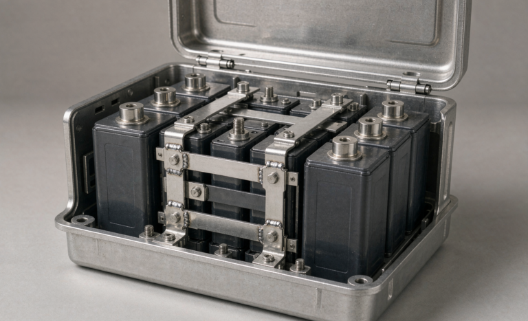
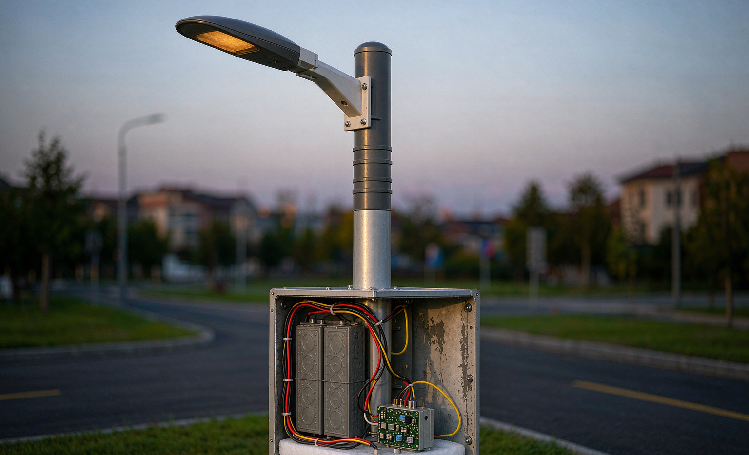
A lockable compartment 400–800 mm above grade, either machined into a larger-diameter pole or supplied as a bolt-on cabinet. It keeps the pack out of standing water, keeps the centre of gravity low, and gives a technician waist-height access. The constraint is internal volume: a 2 kWh sodium pack with its BMS occupies roughly 14–18 litres, which fits an 8U-style tray behind a 350 × 500 mm door. Anti-theft needs a tamper switch wired to the BMS fault line, because a battery box at knee height is an attractive target.
Luminaire-head integrated (“all-in-one”)
Excellent for small formats and fast deployment, but heavy hardware at the top of a pole is a structural penalty. Every kilogram at 6 m adds to the base moment and increases the effective projected area that the wind load calculation must carry. My working limit for head-integrated designs is about 0.6 kWh and 12 kg; above that I move the pack down the pole. Head-integrated units also cook: the enclosure sits directly under a sun-heated luminaire housing, and I have logged 68 °C internal temperatures on a 38 °C afternoon.
Ground vault or buried pit
Thermally the best option by a wide margin — soil at 1 m depth sits between 10 and 18 °C year-round in most temperate climates, which is close to ideal for cycle life. The costs are IP68-rated enclosures, a drainage sump or gravel bed, conduit entry seals, and cable sizing for the longer run. I use vaults on heritage streetscapes where pole-mounted cabinets are not permitted, and on high-capacity poles above roughly 3 kWh.
Whichever you choose, check the cable drop. A 2.5 mm² copper run of 6 m is 12 m of round-trip conductor at 7.41 mΩ/m, so 89 mΩ. At 5 A on a 12 V system that is 0.44 V, or 3.7 % — acceptable. The same run on a 24 V system is 1.8 %, which is one more quiet argument for 8S.
Step 5 — Thermal, Ingress and Lightning: The Three Field Killers
Most premature street-light battery failures I investigate are not chemistry failures. They are installation failures, and they come in three flavours.
- Heat. Cycle life degrades sharply above roughly 45 °C cell temperature. A sealed steel cabinet facing the equator on a summer afternoon runs 20–30 K above ambient. Fix: mount the compartment on the shade side of the pole (north in the northern hemisphere, south in the southern), use a light-coloured or reflective finish, provide a shaded louvre or a solar shield, and never seal the pack inside a foam-lined box with no vent path.
- Ingress. IP65 is the practical minimum for a pole cabinet; IP66 or IP67 for coastal or flood-prone sites. Every conduit entry is a potential leak, so I specify glands with strain relief and a drip loop, plus a breather with desiccant to equalise pressure without pumping humid air through the seal. Conformal coating on the BMS board is cheap insurance.
- Lightning and surge. A street light is a mast with a PV array attached. Type 2 surge protection on the PV input and on the DC bus, with a solid equipment earth of 10 Ω or better, is not optional in thunderstorm regions. I specify 20 kA 8/20 µs minimum on the DC bus and require an earth-bonding inspection at commissioning — a pack that survived three years of thermal cycling will still die in one microsecond if the surge path goes through the BMS.
Verify the assembly against IEC 60529 for the ingress rating, IEC 60068-2 for the thermal and vibration profiles, and IEC 62477-1 for the power conversion equipment. The luminaire and driver carry their own obligations under IEC 60598-1 and IEC 61347-2-13.
Step 6 — BMS, Telemetry and Dimming Logic
The battery management system on a street light does less than a traction BMS but must do it perfectly, because nobody visits the pole. My minimum specification:
- Protection: per-cell over-voltage at 4.05 V, under-voltage at 2.40–2.60 V per the Step 2 decision, over-current at 2× continuous for 10 s, short-circuit hardware latch within 200 µs, and charge lockout above 55 °C.
- Balancing: passive balancing at 50–100 mA is sufficient. Sodium cells arrive well matched, and the sloping OCV means small imbalances produce measurable voltage differences that the balancer can actually see — unlike LFP, where 3 mV per percent of SOC makes passive balancing nearly blind.
- SOC estimation: this is an underrated sodium advantage. At 12–14 mV per percent SOC per cell, a 4S pack shows 48–56 mV per percent — easily resolved by a cheap 12-bit ADC. Voltage-based state of charge on sodium lands within ±5 %; on LFP, with its 2–3 mV per percent plateau, the same circuit drifts ±20–30 % and you end up needing coulomb counting with periodic full-charge resets that an off-grid light may never perform.
- Dimming logic: adaptive profiles that read SOC and step down output when the pack passes below 40 %, hard floor at 20 % with the luminaire held at 20 % output until dawn. Lights that go fully dark at 2 a.m. generate complaints; lights that dim gracefully do not.
- Telemetry: LoRaWAN or NB-IoT reporting SOC, pack temperature, charge/discharge current, cumulative amp-hours and fault codes once per hour. On a 400-pole deployment, remote SOC visibility is what lets you plan truck rolls instead of reacting to 311 calls.
Step 7 — Commissioning, Documentation and Compliance Handover
A good integration ends with a paperwork package, because in three years the person holding it will not be you. My handover folder contains the cell and pack test reports, the UN38.3 summary for the transport classification, the pack’s IEC 62619 / IEC 62620 assessment report for the industrial secondary-cell safety framework, the IEC 62133-2 cell report, the IP rating test evidence, the surge protection specification, the commissioning checklist, and the as-built wiring diagram with torque values.
On site, the commissioning sequence is short and worth writing down:
- Verify open-string pack voltage and cell spread before connection — I reject anything above 30 mV spread on a fresh pack.
- Confirm the charge profile in the controller matches the specified sodium curve, and log the first full charge to confirm taper termination actually fires.
- Run a controlled three-night autonomy test with the PV input disconnected, or a simulated-load discharge at 1C-equivalent down to the BMS floor, and record delivered amp-hours against nameplate.
- Torque the DC busbar and power terminals (M6 at 8–10 N·m is typical), photograph the label, and record the pack serial against the pole ID in the asset register.
- Walk the installed-side thermal image after the first full summer week; any termination running more than 20 K above its neighbour gets investigated.
For European projects, remember that Regulation (EU) 2023/1542 brings a digital battery passport for industrial batteries above 2 kWh from 18 February 2027, and every pole pack above that threshold needs to be traceable to it. For shipping, the 23rd revised edition of the UN Model Regulations introduced UN3551 and UN3552 for sodium-ion cells and batteries; because sodium cells can be transported at 0 V with aluminium current collectors on both electrodes, the logistics profile is materially simpler than lithium. Build that into your freight planning rather than discovering it at the port.
Where This Leaves the Technology
Sodium-ion will not win on energy density, and for street lighting it does not have to. A sodium-ion battery wins on three things that matter enormously at the pole: a charge acceptance window that survives winter without a heater, a sloping OCV curve that makes cheap electronics accurate, and a raw-material profile that is not exposed to lithium carbonate price swings. Second-generation cells now deliver 145–160 Wh/kg at cell level, 3 000–6 000 cycles to 80 % capacity in the field data I have reviewed, and self-discharge below 2 % per month, which is what lets a pole survive a fortnight of fog.
The integration discipline is unchanged from any other custom battery solution I have delivered, whether the cells are sodium or lithium: size from the load, map the voltage window before you buy electronics, control the environment, and document everything. Do those four things and a sodium-ion street light will quietly outlive the warranty with nobody ever thinking about it — which is exactly what good infrastructure is supposed to do.
Frequently Asked Questions
Can I drop a sodium-ion pack into an existing LiFePO₄ solar street light without changing anything?
Usually not without a controller adjustment. The charge ceiling differs (4.00 V per cell versus 3.65 V for LFP), so an LFP preset undercharges a sodium pack by 8–12 %, and the wider discharge window can trip the LED driver’s under-voltage lockout early. In practice you need a controller with a programmable lithium profile or a sodium-specific firmware build, plus a decision on the discharge floor as described in Step 2. The mechanical tray and cabling are normally reusable.
How many nights of autonomy should I design for?
Three nights at 80 % depth of discharge is the standard municipal specification for primary and secondary roads; two nights is common for private commercial and car-park lighting. Designing below two nights in a climate with a pronounced cloudy season is a false economy, because the cost of one truck roll to a dark pole exceeds the cost of the extra cells many times over.
Does a sodium-ion street light need a battery heater?
In most climates, no. Second-generation cells accept charge at 0.2–0.3C down to −20 °C and retain 85–90 % of rated capacity there, which removes the preheating stage that LFP requires. Below roughly −30 °C I still specify a low-wattage pad and an enclosure with insulation, but that covers a small fraction of the installed base.
What is the realistic service life compared with LiFePO₄?
Field-return data I have reviewed for second-generation sodium cells shows 3 000–6 000 cycles to 80 % of initial capacity, against 3 000–6 000 for quality LFP under the same depth-of-discharge regime — broadly comparable. The differentiator is usually temperature history, not chemistry: a pack that spends its summers at 55 °C will underperform either technology. Sodium’s calendar-life data set is shorter, so I recommend specifying a performance guarantee with a defined annual capacity-retention gate in your custom battery solution contract rather than relying on a datasheet cycle number.
Is 12 V or 24 V the better system voltage?
I recommend 8S / 24 V nominal for new installations. The discharge floor at 2.60 V per cell is 20.8 V, comfortably clear of a 24 V driver’s 18–19 V lockout, cable losses halve for the same conductor cross-section, and the MPPT stage runs more efficiently. Keep 12 V (4S) for retrofits and small luminaires below roughly 30 W.
How much does the pack weigh compared with lithium?
At pack level, expect 105–120 Wh/kg for second-generation sodium-ion versus 90–110 Wh/kg for LFP — so a 2 kWh sodium pack is around 22–25 kg installed against 24–27 kg for the lithium equivalent. The advantage is modest and shrinking as sodium matures, which is why I never lead with weight in a custom battery solution proposal; the winter charging and SOC-visibility arguments are far stronger.
What certifications should I demand from the pack supplier?
At minimum: a UN38.3 test summary plus the correct sodium-ion transport classification (UN3551 for cells and batteries, UN3552 where applicable under the 23rd revised UN Model Regulations), an IEC 62133-2 cell report, an IEC 62619 / IEC 62620 assessment for the industrial pack, an IP rating verified to IEC 60529, and environmental testing to IEC 60068-2. For North American projects add UL 1973 for the stationary pack and confirm whether the local authority having jurisdiction requires UL 9540 / UL 9540A for the installation.
Can the sodium pack be transported at a lower state of charge than lithium?
Yes, and it simplifies logistics considerably. Air freight of lithium cells is restricted to around 30 % state of charge, whereas sodium-ion cells using aluminium current collectors on both electrodes can be brought to 0 V and shipped without that constraint under the newer UN3551 / UN3552 entries. Confirm the specific classification with your dangerous-goods adviser before booking, because adoption of the revised regulations varies by carrier and by country.