Sodium-Ion Battery Deployment for Backup Power
I have stood in more equipment rooms at 6 a.m. than I care to count, watching a sodium-ion battery cabinet get rolled off a pallet truck and into a space that somebody swore was ready. In roughly one out of four of those mornings, the space was not ready. The doorway was 40 mm too narrow. The floor slab was rated for office loading. The network drop that the monitoring contract assumed would be there had been deleted in a value-engineering pass two years earlier. None of those problems are electrochemistry problems, and none of them show up on a cell datasheet — but every one of them can push a backup power project by three weeks.
This piece is the deployment counterpart to the design and integration work I have written about elsewhere on this site. Design decides what a sodium-ion battery system can do. Deployment decides whether it ever does it. What follows is the field sequence I run on commercial and light-industrial backup projects: seven phases, roughly ninety days from dock to signed acceptance, with the numbers I actually use as go/no-go gates. Some of it is generic energy-storage practice. Several parts are specific to sodium chemistry, and those are the parts that bite teams who assume a sodium-ion pack behaves like the LFP they replaced.
Why Backup Deployment Deserves Its Own Playbook
Backup power is a rare-event service with asymmetric penalties. A solar-storage battery that underperforms loses revenue every single day, so somebody notices in week one. A backup battery that is quietly broken can sit unnoticed for eighteen months, and then a grid event arrives and the facility finds out in the worst possible way. That asymmetry changes what deployment has to prove. You are not commissioning an energy asset; you are commissioning a promise, and the only honest evidence of that promise is a logged, instrumented, full-power transfer under real load.
Sodium-ion changes the deployment picture in three specific ways, one of which is a genuine simplification and two of which are new work.
The simplification is cold. A sodium ion battery holds roughly 85–90% of its rated capacity at −20°C and can accept charge at 0.2–0.3C at that temperature, where an LFP pack needs a pad heater and a charge lockout below 0°C. On unheated sites — telecom huts, remote pump stations, substation control rooms — that removes an entire subsystem from the install: no heater mat, no heater contactor, no heater control loop, no parasitic load to size in the autonomy calculation. I have taken 6–9% off installed capex on cold-climate backup jobs purely by deleting the thermal hardware.
The first new work item is the zero-volt shipping state. Sodium cells tolerate discharge to 0 V without the copper-dissolution damage that destroys a lithium cell, which is why several manufacturers ship sodium-ion packs fully discharged as a transport-safety measure. That is a genuine logistical advantage, but it means your “unbox and energize” script is wrong. A pack that arrives at 0 V per cell requires a controlled first charge with a proper formation ramp before it can be capacity-verified, and that costs you a day you did not budget.
The second new work item is documentation, and specifically transport classification. Sodium-ion batteries now travel under their own UN numbers — UN3551 for sodium-ion batteries shipped alone and UN3552 for cells contained in or packed with equipment, both introduced in the 66th edition of the IATA Dangerous Goods Regulations. They sit alongside the lithium numbers engineers know by heart: UN3480 and UN3481, with the familiar state-of-charge limits. If your receiving team, your freight forwarder, or your insurer is still filing sodium-ion under lithium paperwork, the shipment will be delayed at the worst possible moment and your year-three audit trail will have a hole in it.
Phase 0 — The Fourteen-Point Site Readiness Gate
Nothing ships until this gate is closed. I run it as a written checklist with photographs, because the alternative is discovering a blocker on install day when the crew is already on the clock.
Structural and Spatial
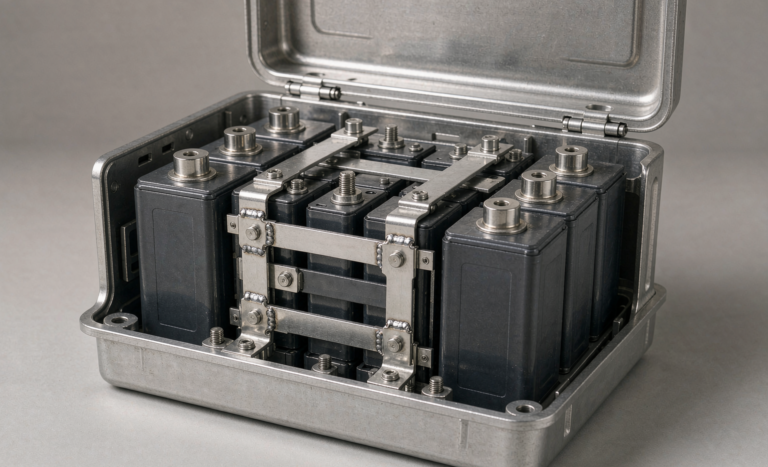
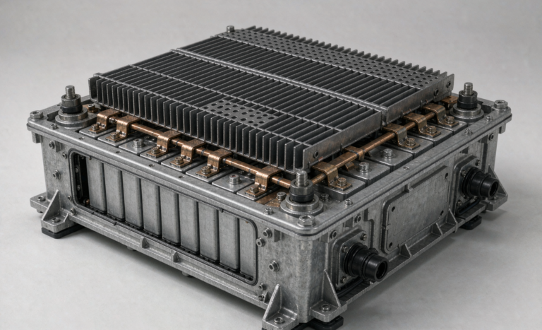
- Slab loading. A 100 kWh sodium-ion cabinet weighs 1.2–1.8 tonnes depending on module layout, and that is before you add the inverter. Office floors are commonly rated around 4–5 kN/m². Get the point load checked against the actual footprint, not the room average.
- Access path. Measure every door, corridor, lift, and turn on the route — not the room itself. Cabinets are typically 1,000–1,200 mm wide and 2,000–2,200 mm tall. I have seen a project lose eleven days to a stairwell that was 30 mm short.
- Clearances. NFPA 855 drives indoor spacing: on the order of 900 mm between energy storage units and to walls, with one-hour fire separation above certain capacity thresholds. Verify against your local adopted code, because authorities having jurisdiction differ on thresholds.
- Seismic and anchoring. Get the bracket pattern and anchor spec into the submittal early. Post-installed anchors into a hollow-core slab are a completely different conversation.
Environmental and Electrical
- Ambient range. Design the room for 15–30°C if you can. Sodium-ion tolerates far wider on both ends, but calendar ageing roughly doubles for every 10 K rise, and that rule does not care which chemistry you bought.
- Ingress. IP54 minimum indoors, IP65 outdoors, with ePTFE venting for condensation management. Check the rating after cable glands are installed, not on the enclosure nameplate.
- AC input and protective devices. Confirm available fault current, breaker ratings, and that the earthing arrangement matches what the inverter expects.
- Surge protection. Type 1 or Type 2 at the service entrance per UL 1449 4th edition, plus a Type 2 at the sub-board, and DC surge protection on any long PV or DC runs.
- Cable route and length. On a 48 V architecture, a 12 kW inverter pulls about 250 A. Plan the room around keeping DC runs to 2–3 m rather than buying thicker copper — 4/0 AWG only buys you so much.
- Network. A wired drop at the cabinet, plus RS-485 or Ethernet to the BMS. If the site uses a segmented OT network, get the VLAN and firewall rules opened before install week.
- Load panel identification. The critical-load sub-board must be physically identified and mapped. This is the single most common source of commissioning-day arguments.
Programmatic
- Shutdown window. Agree the outage slot with the facility in writing, including who signs the permit.
- Authority correspondence. Permit number, inspection sequence, and the inspector’s name.
- Escalation path. A named person with authority to stop work, on both sides.
Phase 1 — Dock-Side Acceptance
Every defect caught at the dock costs an afternoon. The same defect caught after energization costs a week and usually a re-mobilisation. I spend ninety minutes here, every time, on every unit.
Start with transport evidence. Read the shock and tilt indicators — I specify a 5 g threshold on the recorder and treat any trip as a hold, not a rejection, pending inspection. Photograph the indicators before the crate is opened, because once the pack is on the floor the argument about who caused the event becomes unwinnable. Confirm the shipping state: if the pack was shipped at a partial state of charge, expect somewhere around 30% for a lithium-format pack; if it was shipped near zero volts, verify that the zero-volt state is documented and intentional rather than a fault.
Then the electrical checks, in this order:
- Insulation resistance. 500 V DC between the pack terminals and the enclosure, and reject below 1 MΩ. IEC 62619 sets a floor of 100 Ω/V, which for a 500 V system is only 50 kΩ — in my experience anything under a megohm on a new pack means moisture, a pinched harness, or a manufacturing defect, and I do not energize it.
- Cell voltage spread. At 40–60% state of charge, a spread above 30 mV across the string is a reject. On a fresh pack it should be well under that.
- Terminal torque. Verify with a calibrated wrench rather than trusting a factory mark: M6 at 8–10 N·m, M8 at 12–16 N·m, M10 at 20–25 N·m. Torque markings are for later audit, not for acceptance.
- Documentation match. Serial numbers on modules against the packing list, the UN 38.3 test summary (mandatorily available since 2020), and the certificate references for IEC 62619 and UL 1973 as applicable.
Log all of it into the asset record on the spot. A custom battery solution for a multi-site fleet lives or dies on that serial-to-site mapping when a warranty question arrives three years later.
Phase 2 — Mechanical Set and DC Termination
More field failures originate here than in the cells, and it is not close. On the robotics and industrial fleets I have supported, mechanical and connection faults have accounted for roughly 40% of returned units against under 20% for genuine cell degradation. Backup power is no different.
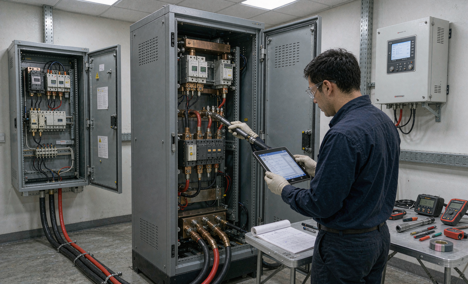
Set the cabinet on its anchors, shim level, torque the anchors, and photograph the torque marks. Terminate DC with the manufacturer’s specified lug and crimp die — a hydraulic crimp on the wrong die is the classic latent defect that passes commissioning and fails in month nine. Route cables so that no conductor carries mechanical load, because a cable pulling on a terminal will eventually loosen that terminal, and a loose DC terminal on a 250 A circuit is a fire. Torque to spec, mark, and schedule a re-torque at the first 50 operating hours.
One step that gets skipped constantly: DC-link pre-charge. An inverter front end presents several millifarads of capacitance, and closing a contactor into it looks, electrically, like a bolted fault. Go through a pre-charge resistor — 10–22 Ω at 50 W is typical for this size — and confirm the DC bus reaches roughly 90% of pack voltage before the main contactor closes. On a 10 mF bus at 51.2 V through 20 Ω, that is about a second. If your installers are closing straight into the bus, you are welding contactors on a schedule.
Phase 3 — First Energization, With a Sodium Twist
If the pack arrived at a normal partial state of charge, first energization is unremarkable: pre-charge, close, verify the BMS is reporting every cell and every thermistor, confirm no latched faults, then run a controlled charge to full with balancing.
If the pack arrived near 0 V per cell — which is a real and legitimate shipping mode for sodium-ion, and the reason several of my clients chose the chemistry — the script changes. You cannot capacity-test a pack that has never been formed, and you cannot trust a state-of-charge estimate derived from an open-circuit voltage curve at a point where the curve is poorly conditioned. Run the manufacturer’s formation ramp, hold at the top for a full balancing pass (8–24 hours is normal on a large string), then perform a full-capacity discharge test to establish the baseline. Budget a calendar day for this and tell the facility in advance, because “the battery is on site but not available” is a sentence that damages trust faster than a two-day slip announced up front.
Either way, establish and record the baseline before the site goes live: capacity at C/5, DC internal resistance per module, and the resting cell spread. Without that baseline you have no defensible way, in year two, to argue whether a battery pack has degraded or was always like that. I have won and lost warranty claims on exactly this point. These are the same three numbers our drone battery teams log on every pack before it leaves the bench, and for the same reason: capacity, resistance, and spread are the only language in which a degradation argument can actually be settled.
Phase 4 — Transfer Testing, Load Banking, and the Deliberate Outage
This is the phase that proves the promise, and it is the phase that gets compressed when the schedule slips. Do not compress it.
Test the transfer chain before you trust the load. For IT and control loads, IEC 62040-3 classifies uninterruptible behaviour in the millisecond domain, and a properly designed static transfer should complete well inside 20 ms — fast enough that servers and PLCs do not see the event at all. A mechanical automatic transfer switch operating in the 50–100 ms range is fine for lighting and motor loads and unacceptable for a server room. Know which one you have, and know what your load actually tolerates, before you schedule the test.
Then load-bank it. Run at 100% rated load for 30–60 minutes and record the data that matters: minimum DC bus voltage, minimum individual cell voltage under load, and temperature rise at every monitored point. Follow with the surge profile — motors and compressors at 5–7× locked-rotor current for one to three seconds — because a backup system that passes a resistive load bank and then collapses when the chiller starts is a system you have not tested.
Finally, do one planned real outage with the facility operating normally. Kill the mains, let the system carry the load for a defined period, restore, and confirm the return transfer and the recharge behave. I insist on this even when the load bank results are perfect, because a real outage exercises the earthing, the generator interface, and the human response in a way no test script does. Schedule it with the facility, log it, and keep the trace.
Phase 5 — Telemetry and Alarm Design
The monitoring deliverable is the one nobody writes down, and it is the one that determines whether anyone notices a problem before the outage that matters. I specify it as a hard requirement, not a nice-to-have.
At minimum, the point list over Modbus TCP or CAN should include: individual cell voltages, at least two temperature points per module, pack current, state of charge, state of health, DC internal resistance trend, contactor status, and a latched fault register with timestamps. Insist on an open register map. A BMS that only speaks a private hexadecimal protocol is a system you cannot integrate, cannot audit, and cannot replace — I have refused procurement on that basis.
Alarm severity needs to be designed, not inherited. I use four tiers — informational, warning, critical, trip — and I am aggressive about demoting anything that fires spuriously, because an operations team that learns to ignore alarms has no alarms. A cell spread warning at 30 mV is informational; 80 mV is a warning; 150 mV is critical and grounds the unit. DC internal resistance at 1.15× baseline means schedule attention; 1.3× means plan replacement; 1.5× means retire. Those thresholds need to be in the commissioning document, not in a commissioning engineer’s head.
Phase 6 — Float, Cycling, and the Standby State of Charge
Backup batteries spend their lives waiting, and how they wait decides how long they live. Two rules govern this, and both are counter-intuitive to facilities teams who grew up on lead-acid float charging.
Do not hold at 100%. Sitting at full charge accelerates calendar ageing on essentially every lithium and sodium chemistry. I park standby sodium-ion between 40% and 60% state of charge, which also leaves headroom for regenerative or return events. Sodium-ion self-discharge runs somewhat higher than LFP — on the order of 1–3% per month against roughly 1–2% — so the dormant period needs a top-up rule. I specify a check every four to six weeks rather than a continuous trickle.
Exercise it on a schedule. A monthly verification discharge to roughly 80% depth of discharge, or 30 minutes at full rated load, whichever the facility tolerates, does two things: it proves capacity and it keeps the state-of-charge estimate honest. Sodium-ion open-circuit curves are relatively flat across the mid-range, which makes voltage-based state-of-charge estimation weak; coulomb counting needs periodic reset points to stay accurate. If you never exercise the pack, the fuel gauge drifts and the first time anyone finds out is during a real outage. We see the identical failure mode on a residential home energy storage system, just in a smaller enclosure: flat mid-range OCV means the estimate drifts unless the operating profile gives it periodic reset points.
Temperature is the quiet killer. Calendar ageing roughly doubles for every 10 K rise in average cell temperature, which means a cabinet sited against a sun-exposed wall can lose years of life for no electrical benefit. If the only available spot is hot, ventilate it — the cost is trivial next to a premature replacement.
Phase 7 — Pilot, Rollout, and the Ten-Item Acceptance Gate
For fleets, I do not go straight to full deployment. Run three to five sites through a 90-day pilot covering at least one real grid event, then hold a formal review before releasing the remaining sites. Every multi-site rollout I have been involved in has changed something after the pilot — usually the alarm thresholds, occasionally the standby state of charge, once the entire cabinet location strategy.
The acceptance gate, in the order I sign it:
- Insulation resistance at 500 V DC — reject below 1 MΩ.
- Resting cell spread at 40–60% SoC — reject above 30 mV.
- Capacity at C/5 — at or above nameplate.
- DC internal resistance recorded as the baseline for future comparison.
- Pre-charge to 90% of bus voltage within specification.
- Full-load soak: maximum cell temperature at or below 55°C, spread at or below 8 K, no derating.
- Transfer time within the load’s tolerance, timed, three times.
- Generator or mains recharge behaviour verified, including AC input current limit.
- Terminal temperature rise acceptable after a load run; anything above 30 K above ambient gets investigated.
- Telemetry verified end to end — every point on the list populating, and a test alarm reaching a human.
Spare strategy belongs in this phase too. For a fleet, hold 10–15% of unit count as spares, add the repair turnaround time multiplied by the monthly replacement rate, and stagger the high-duty sites so failures do not synchronise. Sodium-ion’s supply chain is younger than LFP’s, so I carry a slightly deeper spare pool than I would for an equivalent lithium battery fleet. That said, the chemistry is less mechanically fussy than a semi-solid state battery, which needs its stack pressure held somewhere between 0.05 and 0.30 MPa through the whole service life — an extra variable I would rather not hand to a facilities team that has no way to measure it.
Compliance and the Documentation Package
The documentation you produce during deployment is what protects you in year three, when an inspector, an insurer, or a warranty claim arrives. Build the package as you go rather than reconstructing it later.
At the cell and pack level: the UN 38.3 test summary covering T.1 through T.8, with transport classification under UN3551 or UN3552 for sodium-ion rather than the lithium UN3480 series. At the equipment level: IEC 62619 for industrial secondary cells and batteries, IEC 62477-1 for power electronic converters, UL 1973 where the North American market requires it, and IEC 62133-2 where portable or small-format equipment is in scope.
At the installation level: NFPA 855 for stationary energy storage, UL 9540 and the UL 9540A thermal runaway propagation assessment where the authority having jurisdiction requires installation-level data, IEEE 1547 for interconnection, and the local electrical code for clearances and working space. For European projects, note that EU 2023/1542 brings the battery passport into force from February 2027 — the state-of-health and material data that passport wants is exactly the data your commissioning baseline establishes, so capturing it properly now is not just compliance overhead, it is free preparation.
Keep the commissioning traces with the asset record: the insulation readings, the load-bank log, the transfer timings, the baseline DC internal resistance. Those four artefacts settle almost every early-life dispute I have been asked to adjudicate.
Frequently Asked Questions
How long does a sodium-ion backup deployment actually take on site?
For a single 50–100 kWh cabinet in a prepared room, plan five to eight working days: one for set and termination, one for energization and baseline, one for load banking and transfer testing, and the balance for inspection, punch-list closeout, and telemetry handover. If the pack ships at 0 V and needs formation, add a day. If the room is not actually ready, add however long it takes to make it ready — which is the single largest source of schedule variance I see.
Can sodium-ion replace an existing LFP backup system one-for-one?
Electrically, usually yes with a voltage-window check, since sodium cells run a lower nominal voltage around 3.0 V against roughly 3.2 V for LFP, so string counts differ for a given bus voltage. The real differences are in the BMS configuration and the thermal hardware: you may be able to delete the heater and its control loop entirely, but you must re-verify the charge voltage limits, the balancing thresholds, and the state-of-charge model against the sodium curve. Treat it as a re-commissioning, not a swap.
Does the zero-volt shipping state damage the pack?
No, and that is precisely why manufacturers use it. Sodium cells do not suffer the copper dissolution and subsequent internal shorting mechanism that makes deep discharge destructive in lithium-ion. It is a transport-safety feature. The practical consequence is purely procedural: a 0 V pack needs a controlled formation charge and a baseline capacity test before it enters service, and that takes time you must schedule.
What standby state of charge should I hold?
I specify 40–60% for standby sodium-ion backup. Holding at full charge accelerates calendar ageing, and leaving headroom above the target means any recharge event has somewhere to go. Pair it with a top-up check every four to six weeks to offset the slightly higher self-discharge rate, and a monthly exercise discharge to keep capacity verified and the state-of-charge estimate calibrated.
How often should the backup system be exercise-tested?
Monthly for a functional verification discharge, and annually for a full-capacity test at C/5 against the commissioning baseline. The monthly test is what catches problems — a contactor that did not close, a load that was quietly moved onto the non-critical panel, an alarm path that stopped working. The annual test is what quantifies degradation, and it only means something if you have the DC internal resistance and capacity baselines from commissioning to compare against.
Do I still need heating for a cold-climate site?
Usually not, and this is one of the strongest arguments for sodium-ion on unheated sites. A sodium-ion battery retains roughly 85–90% of rated capacity at −20°C and accepts charge at low rate at that temperature, where LFP requires a charge lockout below 0°C plus a pad heater. Removing the heater removes capital cost, a control loop, a failure mode, and a parasitic drain that would otherwise eat into your autonomy hours. Verify the specific cell’s low-temperature charge limits with the manufacturer rather than assuming them.
What is the most common deployment mistake you see?
Compressing Phase 4. When the schedule slips, the load bank and the planned outage are the first things cut, and they are the only two activities that actually prove the system works. A backup system that has never transferred under real load is an untested assumption, and the first test will be the one that matters. The second most common mistake is skipping the baseline capacity and resistance measurements, which quietly destroys your ability to make a warranty claim later.
Can one battery serve both backup and daily peak-shaving?
Yes, and it improves the economics, but it changes the state-of-charge strategy and the warranty terms. Daily cycling means the pack is regularly away from its standby reserve, so you need a reserve floor that guarantees the backup autonomy you promised, and you need a warranty that explicitly permits the combined duty cycle. Many manufacturers rate cycle life separately for standby-only and for cycling service. Get that in writing before you design the operating profile, not after the first year of daily discharge.