Semi-Solid State Battery Integration for Storage
I am Karl Huang, a senior lithium battery engineer, and over the last few years I have spent more time arguing about bolts, Belleville washers and torque specifications than about cathode chemistry. That is not a complaint. It is a statement about where stationary storage projects actually succeed or fail. When a semi-solid state battery system underperforms in the field after eighteen months, the cell is almost never the villain. The module that stopped holding pressure, the busbar that relaxed, the NTC that was glued to the wrong face of the cell — those are the villains.
This article is the integration companion to our design, testing, manufacturing and safety work on semi-solid cells for stationary storage. Those articles ask whether the cell is good. This one asks a different question: given a good semi-solid state battery, how do you build a rack, a cabinet and a commissioning procedure around it that still meets its storage warranty in year fifteen? Everything below comes from racks I have signed off on, teardowns I have run, and a handful of painful field returns I would rather not repeat.
Why Integration, Not Cell Selection, Decides Whether a Semi-Solid Storage Project Reaches Year 15
Here is the framing I use with customers who arrive with a cell datasheet and a target price per kWh. Cell selection sets the ceiling. Integration sets how much of the ceiling you keep. In conventional liquid lithium battery storage, that gap is modest: a well-built LFP rack typically delivers 80–90% of the cell’s datasheet cycle life because the cell is mechanically forgiving. Liquid electrolyte fills every gap, tolerates modest dimensional change, and keeps ionic contact even when the stack relaxes a little.
A semi-solid cell does not grant that tolerance. It carries dramatically less free electrolyte, which is exactly what buys you the safety and energy-density advantages, but it also means ionic contact at the electrode–electrolyte interface depends far more on mechanical compression being maintained. Remove the pressure and you have not created a safety problem — you have created an impedance problem, and impedance is what the grid operator notices as lost revenue.
So the integration discipline for semi-solid storage has one job above all others: maintain a designed contact pressure across the active stack area, uniformly, for the full service life, across the full temperature and state-of-charge range, while still removing heat and surviving seismic events and truck transport. Almost every design decision below is a consequence of that sentence.
Stack Pressure Is the Primary Integration Variable — and the Enclosure Must Not Carry It
If you take one number from this article, take this one: most of the semi-solid cells we have worked with specify a stack pressure window of roughly 0.05–0.30 MPa applied uniformly over the active area. That is a low number in absolute terms — 0.1 MPa is about one atmosphere — but it must be uniform, and it must persist.
Where the 0.05–0.30 MPa Window Comes From
The lower bound is set by interfacial contact. Below roughly 0.05 MPa, the semi-solid electrolyte layer loses conformity with the electrode surface, local current density concentrates at contact points, and you grow lithium filaments or accelerate local SEI growth precisely where you can least afford it. The upper bound is set by the separator and the electrode coating: compress too hard and you close porosity, squeeze electrolyte out of the coating, and raise ionic resistance — the same failure you were trying to avoid, reached from the other direction. There is also a mechanical ceiling from the cell can or pouch seal.
The practical consequence is that the window is narrower than it looks, and the cost of being outside it is asymmetric. Slightly too much pressure costs you a few percent of capacity. Slightly too little costs you cycle life, and it does so quietly.
Choosing the Compliance Element: Disc Springs, Foam, or Both
You cannot simply bolt a stack of cells between two steel plates and declare the pressure correct. Cells swell. They swell reversibly with state of charge — typically 1–3% thickness excursion between empty and full for cells with silicon-bearing anodes, less for graphite-dominant designs — and they swell irreversibly a little over life as the SEI thickens and gas forms during the first formation cycles. If your compression structure is rigid, that swelling converts directly into a pressure spike, and the pressure spike converts into closed porosity and permanent capacity loss.
So you need compliance. Three options, and in stationary storage I almost always end up specifying a combination:
- Belleville (disc) spring stacks. High spring rate, low creep, predictable over 20 years, and — critically — the force–deflection curve can be designed to be nearly flat over the working range, so a 2% thickness change produces only a small pressure change. Downside: cost, height, and a nasty sensitivity to the exact stack arrangement (series vs parallel disc orientation changes everything).
- Polymer foam / silicone compression pads. Cheap, thin, doubles as an electrical and thermal buffer, and it accommodates thickness variation across the stack. Downside: compression set. A foam that loses 10–20% of its original thickness after a decade at elevated temperature has quietly taken your pressure with it.
- Hybrid: rigid frame sets the nominal gap, disc springs supply the force, thin low-modulus foam distributes it. This is my default. The frame and springs own the pressure budget; the foam only owns uniformity.
Tolerance Stack: Why a ±0.5 mm Cell Thickness Spread Can Eat Half Your Pressure Budget
Engineers who are new to semi-solid integration consistently underestimate the tolerance stack. Work it through. A 20-cell prismatic stack with cells specified at 20 mm ±0.4 mm has a worst-case length spread of ±8 mm. If your compression element is a foam with a working deflection band of 3 mm, you are already out of spec before you cycle the cell once.
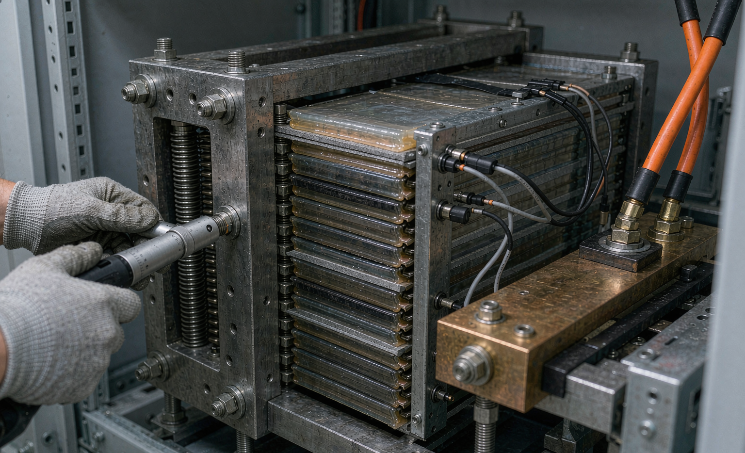
The fix is not tighter cells — that costs money you will not get back. The fix is a frame with an adjustable or shimmed hard stop, so the gap is set by the structure and the foam only has to absorb the residual. On one 1 MWh project we cut pressure variation across the string from ±35% to ±8% purely by adding a shimmed end plate and specifying an incoming cell thickness gauge on the goods-in procedure. That is integration work. It is not glamorous and it is not optional.
Pressure Decay Over 20 Years — Designing the Loss Budget Instead of Discovering It
A stationary storage asset is sold with a 10–20 year warranty. Your compression system must still be inside the window at the end of it. That means you design a loss budget, the same way you would design an accuracy budget for a measurement instrument.
The Four Decay Mechanisms
- Foam compression set and creep. Temperature-accelerated. At 35–40 °C cell temperature — entirely normal in a poorly ventilated container — silicone foam can lose 10–25% of its compressive load over ten years. This is the dominant mechanism in foam-only designs.
- Bolted joint relaxation. Not the bolt yielding; the joint surfaces embedding. First 100–200 hours are the worst, which is why re-torque is a commissioning item, not a maintenance afterthought.
- Polymer creep in the cell itself. The separator and binder relax under sustained load. Small, but real, and it is why a pressure that starts at the top of the window is safer than one at the bottom.
- Thermal cycling ratcheting. Every cycle of expansion and contraction gives the joint a small permanent set. In a daily-cycling solar application that is 3,650–7,300 thermal cycles over a decade. This is the mechanism that separates stationary storage from EV packs: an EV pack may see a comparable number of cycles but over a much shorter calendar period, and it is usually out of service before ratcheting matters.
A Worked Pressure Budget
Target 0.15 MPa mid-window. Set the as-built initial pressure at 0.20 MPa. Allocate the loss budget: foam creep −0.04 MPa, joint relaxation after re-torque −0.01 MPa, cell polymer creep −0.015 MPa, thermal ratcheting −0.015 MPa. End of life lands at 0.13 MPa, still comfortably inside the window with margin for measurement error. If your supplier’s foam data sheet cannot tell you the ten-year compression-set figure at 40 °C, that is a procurement finding, not an engineering assumption — go get the data or change the design.
EIS Lets You Separate Pressure Loss From Chemistry Aging
This is the part of semi-solid integration that I find most under-used, and it is the reason I insist on electrochemical impedance spectroscopy capability in any storage commissioning procedure involving a semi-solid battery.
The Two Signatures
When a semi-solid module’s DCIR rises, there are two broad causes, and they need opposite responses:
- Loss of stack pressure raises the high-frequency intercept — the ohmic, contact-dominated part of the spectrum. On a Nyquist plot, the whole curve slides to the right. The kinetic semicircle barely changes shape.
- Chemical aging (SEI thickening, lithium inventory loss, electrolyte depletion) grows the mid-frequency semicircle and the low-frequency diffusion tail. The high-frequency intercept stays put.
If you only measure DCIR with a DC pulse — which is what 95% of commercial BMS units do — both mechanisms look identical: resistance went up, cell got worse. You then do the expensive thing (replace modules) when the cheap thing (re-torque the end plate) was correct, or vice versa.
Turning This Into a BMS Alarm
You do not need a laboratory potentiostat in every cabinet. You need three things:
- A per-module DCIR baseline captured at commissioning under a defined state of charge, temperature and current step, with the raw voltage trace stored, not just the computed number. Without a trace you cannot re-analyse later.
- A periodic EIS spot check — annually, or on any module that trips a DCIR threshold. A single-frequency measurement at two frequencies (say 1 kHz and 1 Hz) is enough to separate intercept shift from semicircle growth.
- Optional but valuable: a thin-film load cell or strain gauge in the end plate. Costs a few dollars per module, routed into the BMS as an analogue channel. It converts pressure from an inferred quantity into a measured one, and it turns a mysterious impedance rise into a one-line diagnostic.
On one installation this paid for itself in a single site visit: six modules flagged with DCIR up 22% against baseline, intercept shifted, semicircle unchanged. The cause was a batch of tie-rod nuts installed without a calibrated wrench. A two-hour re-torque restored five of the six. Without the intercept-versus-semicircle distinction, we would have quoted six module replacements and a container outage.
The Compression Pad Is a Thermal Insulator — Resolving the Pressure-vs-Heat Conflict
Here is a conflict that every semi-solid storage integrator hits and few anticipate. The material you want for pressure uniformity — a soft, compliant, closed-cell polymer foam — is also an excellent thermal insulator. You are inserting a thermal barrier between the cell and your cooling path.
Numbers That Matter
Typical silicone compression foams sit around 0.1–0.3 W/m·K. Thermally conductive gap-filler pads sit around 1.5–3.0 W/m·K, an order of magnitude better, but they have poor compression recovery and will take a permanent set that destroys your pressure budget. Do the arithmetic on a 2 mm layer across a 0.05 m² cell face: at 0.2 W/m·K and 40 W of cell heat, you get a 16 K temperature drop across the pad. At 2.0 W/m·K, 1.6 K. Same heat, ten times the gradient.
Then remember that calendar aging roughly doubles for every 10 K increase in cell temperature. A 16 K self-inflicted penalty is not a thermal design detail; it is a warranty claim you have written in advance.
Three Workable Architectures
- Rigid frame + thin high-k pad + minimal foam. The frame and disc springs carry the pressure; the foam is only a thin uniformity layer (0.3–0.5 mm) whose creep contribution is negligible. Best thermal performance, highest mechanical cost. My preference for high-rate applications.
- Conductive foam composites. Filled silicone foams reaching 0.6–1.2 W/m·K while retaining reasonable compression set. A genuine compromise, and the right answer for most C-rate-moderate storage products. Get the compression-set data at your actual operating temperature, not at 23 °C.
- Side-wall cooling instead of face cooling. If your cell format allows it, extract heat through the large face via a rigid, clamped cold plate that is also the compression structure. Pressure and thermal path stop competing. Highest engineering effort, best long-term result.
Thermal Mapping: NTC Placement Should Follow the Hotspot, Not the Drawing
With less free electrolyte, a semi-solid cell has less convective and conductive internal heat spreading than a flooded liquid cell. The practical effect is that internal temperature gradients are steeper, and the location of the hottest point is less predictable from the geometry alone. Placing two NTCs per module where the CAD model looks convenient is a coin toss.
The procedure I insist on: build three instrumented sample modules with 10–16 thermocouples distributed over the cell faces, terminals and busbars, then run the worst-case duty profile — typically a full-rate charge immediately followed by a full-rate discharge at the top of the ambient range. Record where the maximum actually is, and how much the gradient is. Then place your production NTCs at that measured location and set the BMS derating threshold using the measured delta between the sensor and the true internal maximum.
Two rules follow. First, a sensor that reads 8 K cooler than the true hotspot is worse than no sensor, because it authorises operation that the cell cannot sustain. Second, terminals and busbars need their own thermal surveillance independent of cell temperature — in field teardowns, connection heating is consistently a larger share of thermal incidents than cell heating.
Electrical Architecture — String Sizing, Parallel Strings, and Balance Strategy
String Voltage and the Serviceability Trade
For stationary storage the trend is firmly toward 1500 V DC systems, and semi-solid cells do not change that. Higher string voltage means lower current, smaller copper, lower resistive loss, and fewer parallel paths. But it interacts with integration in two ways worth naming. Higher series counts mean the weakest cell governs the string more aggressively, which raises the value of tight initial capacity and DCIR matching. And serviceability suffers: a 1500 V string is a more hazardous thing for a field technician to work on, which argues for module-level fusing and clearly documented safe-state procedures rather than for lower voltage.
Parallel Strings: Semi-Solid’s Higher Initial DCIR Spread
Semi-solid cells, particularly early production lots, tend to show a somewhat wider initial DCIR distribution than mature LFP cells — in data I have reviewed, coefficient of variation in the range of 5–8% versus 2–4% for a mature liquid line. That matters when you parallel strings, because current divides in inverse proportion to impedance, and the imbalance is self-reinforcing through temperature: the higher-impedance string runs hotter only if current does not redistribute, so the practical effect is usually a static mismatch rather than thermal runaway. Still, specify a matching criterion at procurement, and verify it at goods-in. If the supplier cannot bin cells by DCIR, buy more margin in your thermal design.
Balancing When the OCV Platform Is Flat
Whether passive balancing works depends entirely on the slope of the OCV-versus-SoC curve for your specific semi-solid chemistry. Graphite-dominant designs inherit the flat lithium-ion platform, where the voltage difference between 30% and 70% SoC can be only a few millivolts — passive balancing there is close to useless and you need active balancing or periodic full-charge equalisation. If your anode blend includes silicon, the OCV curve is sloped and passive balancing behaves better. Do not assume. Measure the dOCV/dSoC curve for your cell and size the balancing strategy from it.
This is also where the battery pack design decision about modularity pays off: modules that can be individually isolated, measured and rebalanced at the rack level turn a whole-string problem into a single-module service call.
BMS Parameterization — Do Not Copy Your LFP Curve
The most common integration error I see is a controls engineer loading the previous product’s LFP parameter set into a semi-solid rack and adjusting only the capacity number. Five parameters must be re-derived from cell data:
- Charging voltage limit and taper termination. Semi-solid cells often tolerate a marginally higher upper voltage but are less tolerant of a prolonged constant-voltage hold at high SoC and high temperature. Set taper termination by current (0.02C–0.05C) and then stop — no float.
- Temperature-dependent charge current limits. Reduced free electrolyte generally means higher charge-transfer resistance at low temperature, so the 0 °C hard cutoff and the reduced-rate band just above it should be tighter, not looser, than your LFP values. Apply hysteresis so you do not chatter across the boundary.
- DCIR baseline and alarm thresholds. Set from measured commissioning data, not from the datasheet. Use tiered thresholds: 1.15× schedule a diagnostic, 1.3× plan replacement, 1.5× retire.
- Sensor validation. A failed NTC that reads cold will disable the protection you were relying on. Require plausibility checks — rate-of-change limits, cross-checks against ambient, and a defined safe fallback.
- Communication-loss behaviour. When the BMS loses contact with the inverter or the plant controller, it must fall back to a conservative fixed curve, not hold the last commanded value. Holding last value is how you get an overcharge at 3 a.m.
And one procurement constraint that I now treat as non-negotiable: the BMS must speak an open protocol — CAN 2.0B with a published DBC file, or Modbus with a documented register map. A proprietary hex protocol means you cannot integrate it, cannot audit it, and cannot replace it. I have rejected otherwise excellent hardware on this point alone.
Rack Mechanical, Seismic and Transport: Vibration Is a Pressure Event
A rack is shipped, lifted, set down, and then asked to survive a design earthquake. Every one of those events is a load case on your compression system, and the failure mode is not usually breakage — it is loss of preload.
Design implications:
- Tie rods in tension, end plates in bending. Size the end plate for stiffness first and strength second. A flexible end plate produces a pressure map that is high at the tie rods and low at the centre of the cell face, which is exactly the non-uniformity the cell cannot tolerate.
- Positive mechanical locking. Nyloc nuts, lock washers or thread-locking compound on every fastener in the load path, plus torque witness marks. Vibration plus thermal cycling will back off a plain nut.
- Seismic anchoring. Follow the local code and IEEE 693 where applicable, but also anchor the modules inside the rack, not just the rack to the floor. A module that can shift 5 mm inside its shelf will shift.
- Shipping restraint vs operating compliance. If the same structure must be rigid for transport and compliant in service, add removable transport brackets that are documented as a commissioning removal item — and put that removal on the commissioning checklist with a sign-off, because it will otherwise be forgotten.
Fire and Code: Let UL 9540A Data Set Your Spacing, Not a Rule of Thumb
Semi-solid cells generally demonstrate improved thermal stability and reduced combustible electrolyte volume, which is a genuine advantage. It is not a licence to skip testing. Under NFPA 855 and the UL 9540 listing framework, your separation distances, suppression requirements and installation configuration are driven by test evidence — specifically UL 9540A thermal runaway propagation data at cell, module, unit and installation level.
What I tell customers: the reduced free electrolyte in a semi-solid state battery should reduce the total combustible gas generation during a propagation event, and in the 9540A unit-level data I have reviewed that expectation holds. But the authority having jurisdiction does not accept expectations. They accept test reports. Budget for the installation-level test early, because it is on the critical path for any project above the small-system threshold, and a late discovery that your spacing assumption was wrong can reshape a site layout.
Two integration details that follow from the test data rather than from intuition: gas detection and deflagration venting must be designed against the measured gas composition and generation rate, not against a generic lithium-ion assumption; and the propagation barrier design must be validated with the actual module and compression hardware, because a compression frame is a substantial thermal conduction path that can defeat a barrier that worked fine on the bench.
Grid Interface: Where Semi-Solid Shows Up on the AC Side
IEEE 1547, UL 1741 SA and IEC 62477-1 do not care what is inside your cell. Grid-support functions — voltage and frequency ride-through, reactive power capability, ramp-rate control — are delivered by the power conversion system with the battery as an energy and power source behind it. But your cell chemistry shows up in two places that integration must handle.
First, available power at low temperature and low SoC. Ride-through and ramp events are precisely the moments when you ask for high C-rate from a cold, partly discharged rack. With reduced free electrolyte, the cold-morning DCIR rise can be larger than your LFP experience suggests, and the power your PCS was counting on may not be there. The fix is a derating model in the plant controller driven by measured cell temperature and state of charge, validated by an actual cold-start test at the worst case, not by a datasheet extrapolation.
Second, round-trip efficiency and thermal budget. Semi-solid cells can show slightly higher initial DCIR, which costs a fraction of a percent in round-trip efficiency. That fraction of a percent is heat inside the cabinet, and it compounds with the thermal gradient problem described earlier. Size the cooling for the end-of-life resistance, not the beginning-of-life resistance, or your year-eight summer will look very different from your year-one summer.
Commissioning the First 100 Cycles: Re-Torque, Re-Pressure, Re-Baseline
The first hundred cycles of a semi-solid storage rack are when the mechanical assembly settles and the cells finish their early-life dimensional and impedance changes. Treat this as a defined commissioning phase with checkpoints, not as the beginning of normal operation.
- At installation: calibrated torque wrench on every fastener in the load path, with witness marks and recorded values. Incoming inspection already did: insulation resistance at 500 V DC (reject below 1 MΩ — note IEC 62619 only requires 100 Ω/V, which is 50 kΩ at 500 V; 1 MΩ is an experience-based rejection line), cell voltage spread within 30 mV at 40–60% SoC, and cell thickness gauge against the tolerance stack assumption.
- At 24 hours and again at 168 hours: re-check fastener torque and, if instrumented, end-plate load. The great majority of joint embedding happens here. Re-torque to specification.
- At 500 hours: full re-torque audit and pressure verification, plus the first DCIR and capacity baseline at C/5 under controlled temperature.
- At 100 cycles: re-baseline DCIR and capacity. The early-life impedance change is now largely complete, and this becomes the reference against which all future 1.15× / 1.3× / 1.5× thresholds are judged.
- Throughout: log the full charge curve at least once at each seasonal temperature extreme. You are building the dataset that will let you argue with a warranty claim in year nine.
Formation gas is worth a specific note. Semi-solid cells, like all lithium cells, generate some gas during initial formation. If your design has no accommodation for the resulting thickness increase, the first cycles are when your pressure goes from correct to excessive. Build the accommodation into the compliance element, and verify with a post-formation pressure measurement rather than assuming.
Lifetime Monitoring and the Spare-Module Strategy
Stationary storage is a twenty-year asset sold by companies that may not exist in twenty years. Design the monitoring and spares strategy for that reality.
- Annual pressure audit on a statistical sample of modules — 10% is usually enough to catch a systematic problem, with a full audit if any sample is out of band.
- Annual EIS spot check on the same sample, tracking the high-frequency intercept and the semicircle separately.
- DCIR trend thresholds as above, evaluated at a consistent SoC and temperature or corrected to a reference — an uncorrected DCIR comparison between a January reading and a July reading is meaningless.
- Spare modules: 10–15% of N is the common rule for a fleet; for a single site, size spares by turnaround time multiplied by the expected monthly replacement rate. For semi-solid specifically, hold a slightly deeper spares pool than you would for LFP, because the supply chain is newer and a second-source cell may not be drop-in.
- And a hard rule: if a replacement cell has a different thickness, different pressure specification or different series count for the same rack voltage, it is a re-commissioning, not a swap. Re-derive the pressure budget, the torque values and the BMS setpoints.
What to Put in the RFP: An Integration Specification Checklist
Most of the failures described above were, in origin, specification failures. The customer asked for a kWh number and a cycle-life number and got exactly what they asked for. Here is what I would add to a semi-solid storage RFP:
- Stack pressure window, the as-built initial pressure, the end-of-life minimum, and the measured pressure map across the active area at three points in the cycle.
- Compression element datasheet including ten-year compression set at the maximum operating temperature, not at 25 °C.
- Fastener torque specification with the re-torque schedule, and a statement that the enclosure does not carry stack load.
- Thermal map from an instrumented prototype showing sensor location, measured gradient, and the delta between sensor reading and true hotspot.
- DCIR baseline per module with the raw trace, plus the procedure and conditions for repeating it.
- Open communication protocol: CAN 2.0B with DBC, or Modbus with a register map. No proprietary hex.
- Communication-loss fallback behaviour, stated explicitly.
- UL 9540A test reports at cell, module and unit level, with the installation-level test scoped and scheduled.
- Cold-start power validation at the minimum specified operating temperature and minimum SoC.
- Spare module availability commitment in years, and a change-notification clause for any cell dimensional or pressure-specification change.
None of these are exotic. All of them are cheaper to specify at purchase than to discover at commissioning.
FAQ: Semi-Solid State Battery Integration for Storage
Do semi-solid cells need compression hardware that liquid lithium cells do not?
Not fundamentally — quality prismatic LFP modules also use compression — but the tolerance for getting it wrong is much smaller. A liquid cell loses a little performance when compression relaxes; a semi-solid cell loses ionic contact area, which shows up as rising impedance and lost cycle life. Budget for a real pressure system, instrument it, and verify it at commissioning.
Can I drop semi-solid modules into an existing LFP rack design?
Rarely without mechanical changes. Even when the external dimensions match, the pressure window, the thermal gradient behaviour and the balance strategy are likely to differ. Treat it as a re-commissioning: new compression design or at minimum a new pressure budget, new torque specification, revised BMS parameters, and a new UL 9540A assessment for the combination. A custom battery solution from a supplier who will do that work with you is worth more than a cheaper drop-in that quietly voids the assumptions your rack was built on.
How often should stack pressure be checked in the field?
With instrumented end plates, continuously and for free. Without them, annually on a 10% sample, plus a re-torque at 24 hours, 168 hours and 500 hours after installation. Any DCIR alarm should trigger a pressure check before anything else.
What is the biggest thermal mistake in semi-solid storage integration?
Putting a thick, soft, thermally insulating compression foam in the only heat path and then sizing the cooling system from the cell datasheet. Measure the pad’s thermal conductivity, compute the gradient at your actual heat load, and place NTCs at the measured hotspot rather than at the convenient location.
Does semi-solid integration change my grid-code compliance work?
Not for IEEE 1547 or UL 1741 SA — those are PCS functions. It changes the power-availability model behind them: cold-morning DCIR rise can reduce available power exactly when ride-through and ramp support are demanded. Validate cold-start power by test, and feed a temperature-and-SoC derating model to the plant controller.
Is a 1500 V architecture appropriate for semi-solid storage?
Yes, and it is where the industry is going, but it raises the value of tight initial cell matching and of module-level fusing and safe-state procedures. Specify a DCIR and capacity binning criterion at procurement and verify it at goods-in.
What end-of-life or retirement criteria should I write into the maintenance contract?
Capacity below 80% of nameplate, DCIR above 1.5× commissioning baseline at reference conditions, cell-to-cell voltage spread above 150 mV under load, or measured stack pressure below the specified minimum. The first three are conventional; the fourth is specific to semi-solid and is the one most contracts omit.
Should storage use semi-solid at all, given the integration burden?
It depends on what you are buying. If your constraint is footprint or safety-driven siting restrictions, the higher energy density and reduced combustible electrolyte can be worth the mechanical discipline. If your constraint is purely levelised cost per kWh on an unconstrained site, mature LFP with a well-understood integration path is still hard to beat. The honest answer is that semi-solid in storage is a home energy storage-and-C&I play where space, safety or lifetime energy throughput dominate — and where the integrator is willing to do the mechanical work described above.