Home Energy Storage Integration for New Homes
I have spent fifteen years designing lithium battery packs for everything from a 6S drone battery that has to survive 12 g of launch acceleration to 400 V stationary racks that have to survive twenty years of daily cycling. The hardest projects in that whole range are not the ones with the most demanding electrical specification. They are the ones where I get called in after the drywall is up.
home energy storage integration in a new build is a fundamentally different engineering problem from a retrofit. In a retrofit, the battery is an appliance you bolt onto a finished house, and every compromise is paid for in money: trench a new conduit, upsize a panel, re-route a feeder. In a new build, the battery is infrastructure. The same outcome that costs eight thousand dollars in a retrofit costs a few hundred dollars at framing — because the expensive part was never the hardware, it was access. Once the sheetrock is up, the wall is closed, the roof is shingled, and the concrete is poured, you are no longer doing engineering. You are doing demolition.
This is the playbook I hand to builders and to the electricians who work for them. It is organised around the seven construction milestones where a home energy storage decision either gets made cheaply or gets made expensively. Every number in here is a number I have had to defend in front of an inspector or a homeowner.
Why a New Build Is a Different Engineering Problem
The difference is not the equipment. A 20 kWh LFP cabinet behaves identically whether it is installed in a 1978 ranch or a 2026 spec house. The difference is that a new build has a schedule, and every integration decision has a deadline attached to it. Miss the deadline and the decision reverts to the retrofit cost curve.
Three examples from my own project files:
- Service capacity. A 200 A busbar panel accepted at rough-in becomes a $3,500 panel and service upgrade eighteen months later when the homeowner adds storage, because the backfed breaker has no headroom left. The panel cost delta at construction was about $400.
- Roof penetration. Conduit from the array to the battery location can be routed and flashed while the roof is open. Afterwards, it is a re-roof-adjacent operation that voids the shingle warranty in most jurisdictions and turns every future leak into a finger-pointing exercise between the roofer and the solar contractor.
- Wall structure. A 20 kWh wall-mounted enclosure is 150–250 kg. Anchoring that into studs at 406 mm (16 in) centres with proper blocking is a five-minute conversation with the framer. Anchoring it into finished drywall means opening the wall.
None of these are electrical engineering. They are all integration engineering, and they are all decided before the drywall inspection.
Milestone 0 — Design Lock Before the Permit Set
The single most valuable thing a builder can do is put the home energy storage system on the permit set. Not “provision for future solar.” The actual one-line diagram, the actual equipment location, the actual conduit schedule.
Why: the authority having jurisdiction (AHJ) reviews what is on the plans. If storage appears later as a field change, it is reviewed as an amendment, amendments get queued behind new permits, and your energization date moves by four to ten weeks in a typical US county. I have watched a house sit finished and unoccupied for two months waiting for an amendment review on a battery that was always going to be installed.
At design lock I want five things settled in writing:
- Equipment list with listings. UL 9540 (system), UL 9540A (thermal propagation test report), UL 1973 (battery), and where applicable IEC 62619. The AHJ will ask for the 9540A report specifically, because spacing and fire separation are derived from it, not from the sales brochure.
- One-line diagram showing service, main disconnect, generation, storage, critical-loads panel, and the neutral-to-ground bonding location. One diagram covering all three trades, not three separate diagrams that disagree.
- Equipment location with dimensions and weight, signed off by the framer and the structural engineer if it is a floor-standing unit over about 150 kg.
- Conduit schedule: route, size, fill percentage, and spare capacity.
- Article 220 load calculation that includes the storage inverter as a load, the EV charger, the heat pump, and the electric range. If the house is being sold as “electric-ready,” the load calc has to prove the service is adequate with all of it running, not with most of it running.
Who Owns the Interface
New-build storage fails more often on responsibility than on physics. Three trades touch it: the electrician, the solar/storage installer, and the HVAC contractor if there is a heat pump. When the heat pump’s locked-rotor surge trips the inverter during the first cold snap, all three will correctly point at someone else.
My rule: one contractor holds the single-line and is responsible for energization. Everyone else works to that drawing. This is also why I push builders toward a custom battery solution with a clearly specified interface document rather than three boxes from three vendors — pack, inverter, and gateway from the same design team means the surge compatibility question was answered in the factory, not in the driveway.
Milestone 1 — Space, Structure, and Location
Location is the decision you can never cheaply revisit. Four constraints, in the order they usually kill a layout:
Structure and Anchorage
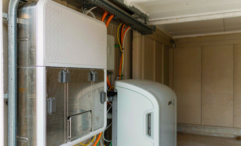
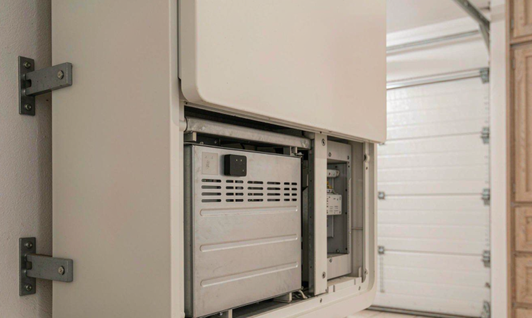
Wall-mounted residential enclosures run 100–250 kg depending on capacity. That is a real point load. At framing, I specify 18 mm (¾ in) plywood backboard spanning at least three studs, with 2× blocking at the top plate height, anchored with structural screws into studs — never into drywall with toggles. Floor-standing cabinets of 300 kg or more need a look at joist span and deflection; a 1.2 t rack in a garage with 2×8 joists at 16 in o.c. is a conversation with the engineer, not with the framer.
Working Clearance
Inspectors cite clearance more than anything else. NEC 110.26 requires a working space 900 mm (36 in) deep, 760 mm (30 in) wide, and 2.0 m (78 in) high in front of equipment that has to be serviced live. Garages fail this constantly because the clearance zone overlaps the parked car. Draw the clearance box on the plan and make sure nothing — water heater, workbench, door swing, storage shelving — is inside it.
Fire Separation and Listing
NFPA 855 governs stationary ESS installation, and most residential AHJs adopt its spacing and separation provisions either verbatim or with local amendments. Some jurisdictions restrict ESS in attached garages entirely; others permit it with a physical barrier or a minimum separation between units. This varies enough by county that I never assume. The installer must pull the local amendment before rough-in, because the answer changes where the equipment goes.
Temperature — The One People Discover Too Late
An attached garage in Phoenix, Las Vegas, or inland California will sit at 45–50 °C on a July afternoon. LFP cells typically carry a charge cutoff at 45 °C cell temperature and a discharge cutoff in the 55–60 °C range, so a hot garage does not destroy the pack — it silently removes hours of usable charging window every summer day, and it roughly doubles calendar-aging rate for every 10 K above the reference.
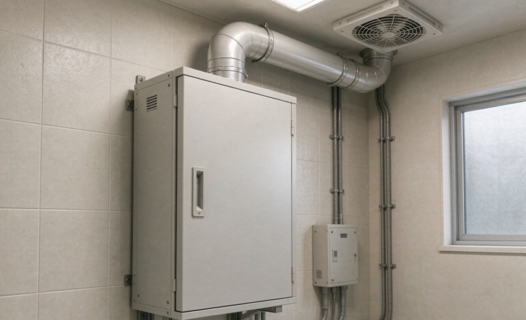
My recommendation in hot climates: put the system in an insulated interior utility room or a conditioned mechanical closet, and reserve that space at framing. In cold climates the mirror problem appears — below 0 °C, charging an LFP pack is prohibited outright because lithium plates onto the anode instead of intercalating, and recovery must have a hysteresis band of roughly +3 to +5 °C. This is precisely the case where I steer clients toward a sodium-ion battery chemistry: it retains 85–90 % of room-temperature capacity at −20 °C and, critically, can accept 0.2–0.3 C charge at that temperature, which deletes the heater, its contactor, its control loop, and its parasitic load from the design entirely.
Milestone 2 — Service Sizing and the 120% Busbar Rule
This is the most common hidden cost in residential storage retrofits, and it is nearly free to avoid in a new build.
NEC 705.12(B) limits a load-side interconnection: the sum of the main overcurrent device and the backfed generation/storage breaker cannot exceed 120 % of the busbar rating. Do the arithmetic on the most common US residential panel:
- 200 A busbar → 200 × 1.20 = 240 A allowance
- Main breaker = 200 A
- Remaining headroom = 40 A
40 A at 240 V is roughly 9.6 kW of inverter output. That is often fine for a modest system and completely inadequate for a whole-house backup design with a 12 kW inverter. The retrofit remedy is a panel upgrade or a supply-side tap; both are four-figure operations requiring a utility outage.
The new-build remedy costs almost nothing. Specify a 225 A busbar panel (270 A allowance → 70 A headroom) or a 320 A meter-main, and the constraint disappears for the life of the house. I also specify the panel with spare breaker positions: a storage system typically consumes four to six spaces (inverter, battery disconnect, PV, critical-loads feeder, surge device, monitoring), and “full panel” is the second most common cause of a change order.
Milestone 3 — Rough-In: Conduit, Backboard, and Grounding
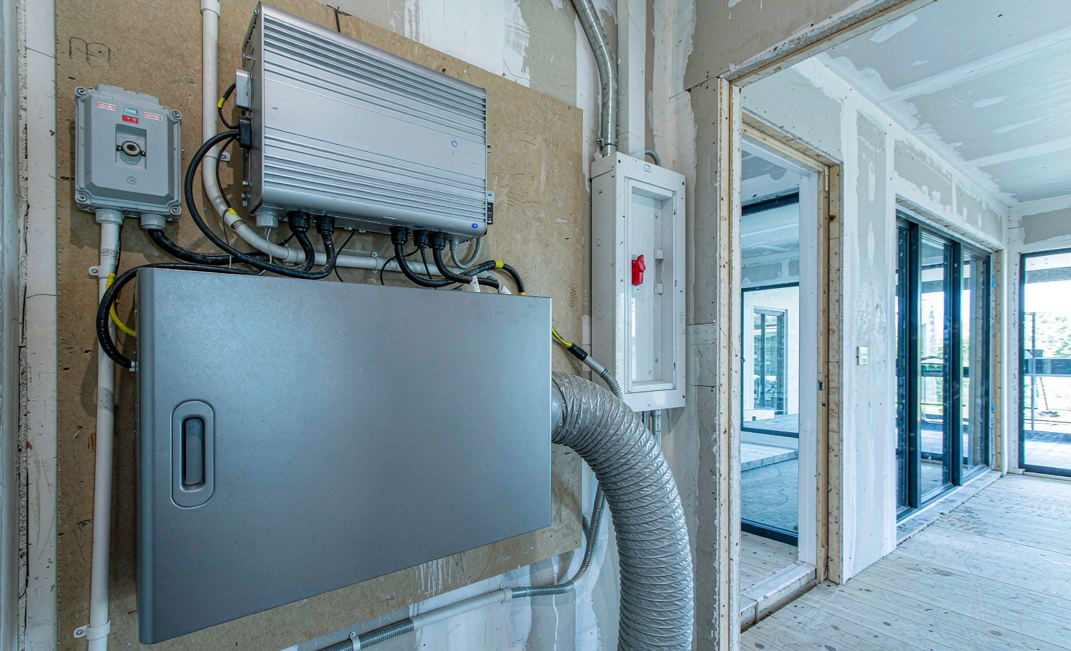
Rough-in is where the new-build advantage is either banked or thrown away. Three items:
Conduit
Every conduit you will ever want between the roof, the battery location, the panel, the EV charger, and the heat pump should go in now. Rules I enforce:
- Size for the future, not the first install: 32–40 mm (1–1¼ in) for array homeruns, 25 mm (1 in) minimum for anything else.
- Total bends between pull points ≤ 360°.
- Every conduit gets a pull string and both ends labelled.
- At least one spare 25 mm conduit from the battery location to the attic and one to the exterior, capped and stung. This single item is what makes a second battery or a generator feeder a one-day job instead of a renovation.
- Derating matters: more than three current-carrying conductors in a raceway triggers NEC 310.15(C)(1) adjustment factors, and a warm garage adds a temperature correction on top. Size conduit for the derated conductor, not the nominal one.
Backboard and Penetration Sealing
The backboard goes up before the rough-in inspection, not after. If the inspector cannot see the mounting structure and the clearance envelope, you will get a correction and a re-inspection fee. Every penetration through the top plate or an exterior wall gets firestopped and sealed to the assembly’s rating — an unsealed penetration is both a code violation and an unconditioned air path that will deposit moisture inside the enclosure.
Grounding Electrode
If the design includes a Ufer (concrete-encased) electrode, it has to be in the pour. There is no retrofit for that. The grounding electrode conductor route to the ESS location is also a rough-in item. Measured earth resistance matters: a single driven rod at 25 Ω or less is the NEC 250.53 threshold for stopping; above that you add a second rod, a ground ring, or a chemical electrode. I want that measurement recorded with a three-point fall-of-potential test at rough-in, because “the ground is fine” is not an answer I can defend later.
Milestone 4 — Topology: Whole-Home vs Partial, Meter Collar vs Subpanel
New construction unlocks a topology that retrofits often cannot use: the meter-collar or meter-socket adapter (sometimes called a MID). Instead of moving selected circuits into a critical-loads subpanel, the adapter sits between the meter and the socket and disconnects the entire service from the grid during an outage. The whole main panel becomes backed up.
- Critical-loads subpanel: works everywhere, requires no utility approval, but forces you to choose at construction which circuits matter — and the homeowner’s answer in month three is usually different from the answer at design time. Material and labour typically lands in the $1,500–3,000 range depending on how many circuits move.
- Meter collar: whole-home backup, no circuit triage, typically less labour. Two catches: it requires the utility’s approval and a compatible meter socket, and that approval can take eight to twelve weeks. Start it at design lock, not at trim-out.
On the DC side, the coupling choice follows the design:
- DC-coupled — PV and storage share a charge controller; single conversion from array to battery, best round-trip efficiency. My default for new construction where PV and storage are installed together.
- AC-coupled — PV and storage each have their own inverter; four conversions from array to load, roughly 5–8 % efficiency penalty, but it is the flexible option when the array comes first and storage follows, or when an existing microinverter array is in play. Requires an inverter certified for AC coupling with frequency-shift curtailment.
- Hybrid integrated — one box, one firmware, coordinated control. For systems under about 10 kW this is the default and the least likely to fail at the interfaces, at the cost of a single point of failure.
Milestone 5 — Protecting the Equipment During Construction
This is the milestone nobody puts on a schedule, and it is where I have seen more batteries damaged than in any electrical failure mode.
Construction sites are hostile to electronics in four specific ways:
- Gypsum and concrete dust. Drywall dust is hygroscopic and mildly conductive. It settles on PCBA, absorbs moisture overnight, and produces leakage currents and intermittent faults that appear months later and are almost impossible to diagnose because the dust is invisible by then.
- Paint overspray and texture spray on vents, displays, and connector faces.
- Moisture from wet trades — curing concrete, plaster, and tile raise interior humidity well above dew point for days.
- Temporary power. Site power from a generator or a temporary pole is dirty: voltage sags, frequency excursions, and switching transients. Never energize or charge a storage system from temporary power, and never use the storage system to run construction loads. Saw and compressor starts are exactly the kind of 5–7× locked-rotor surge that a correctly sized residential inverter will refuse, and the resulting nuisance trips get logged as faults.
My specification is blunt: equipment is delivered after final paint and after permanent HVAC is commissioned and running. If the schedule will not allow that, the enclosure stays in climate-controlled storage, and the installing contractor pays for it. A battery that sits shrink-wrapped on a slab through the wet trades is a battery I will not warranty.
Milestone 6 — Energization, the Idle-House Problem, and Construction Mode
Here is a failure mode that exists only in new construction, and it costs real capacity.
Sequence: PV and storage are energized at trim-out so the house can be conditioned and so the AHJ can sign the final. The homeowner moves in two to three months later. During those months the array produces full output into a house with no load. The BMS does exactly what it was designed to do: it charges the pack to 100 % and holds it there, every day, for ninety days.
At 40 °C cell temperature and 100 % state of charge, calendar aging runs at roughly twice the rate it would at 50 % SoC and 25 °C. Three months at the top of charge in a hot garage is a measurable, permanent capacity loss before the homeowner has used one kilowatt-hour. I have seen 2–4 % of nameplate capacity burned off this way, and it is invisible on the warranty claim because there is no baseline to compare against.
The fix is a construction mode in the commissioning procedure, written into the installer’s scope:
- Set a charge limit of 40–60 % SoC and disable or curtail PV charging during the idle period.
- If the equipment has no software charge limit, physically open the PV disconnect or the DC isolator and energize the battery from the grid at a reduced setpoint.
- Set a maintenance-charge trigger at 30 % SoC, not a continuous float. LFP does not want float; the correct sequence is CC to 0.2–0.5 C, CV to a tail current of 0.02–0.05 C, then stop.
- At occupancy, run the full commissioning: restore the charge limit, perform one full charge with a 2–6 hour top-of-charge hold for passive balancing, and record the C/5 capacity baseline.
There is a second, quieter new-build issue here: monitoring. Most residential gateways commission over Wi-Fi, and in a new house the homeowner’s router does not exist yet. The system goes in dark, and nobody finds out until the homeowner tries to log in for the first time. Specify a hardwired Ethernet drop at the equipment location and a temporary commissioning hotspot. A monitoring gap during the first weeks is exactly when you most want data.
Milestone 7 — Commissioning Acceptance Tests Before Handover
Commissioning is not “it turned on.” These are the tests I require, with recorded values, before I sign off on a residential system:
- Insulation resistance at 500 V DC, pack disconnected from the inverter: reject below 1 MΩ. Note that IEC 62619 only requires 100 Ω/V, which is 50 kΩ at 500 V — the 1 MΩ threshold is a field-practice limit, not a standard limit, and it catches far more problems.
- Cell voltage spread at 40–60 % SoC: reject above 30 mV before balancing.
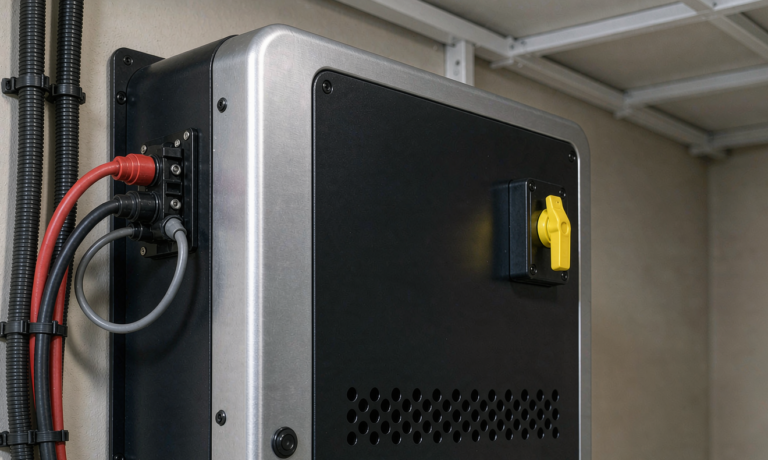
- Torque audit with a calibrated wrench, not a factory label: M6 at 8–12 N·m, M8 at 12–16 N·m, M10 at 20–25 N·m, plus torque marks.
- C/5 capacity test: delivered capacity must meet or exceed nameplate.
- DCIR baseline per module, with the raw voltage and current trace retained, not just the computed number. This is the number that makes every future warranty conversation possible; the operating thresholds I use are 1.15× baseline for scheduled service, 1.3× for planned replacement, 1.5× for retirement.
- Full-load run: 100 % rated load for 30–60 minutes, recording minimum DC bus voltage, minimum cell voltage, and temperature rise. Cell temperature should stay below 55 °C with a module ΔT under 8 K, with no derating.
- Transfer timing: three measured transfers. Static transfer under 20 ms keeps IT equipment and most furnaces alive; 50–100 ms mechanical ATS will drop them. Measure it, do not assume it.
- Generator or grid recharge test including the AC input current limit set to 80 % of the source’s continuous rating.
- Infrared scan at above 50 % load: any termination running more than 20 K above ambient gets reworked; more than 30 K stops the job. A good crimp is 0.2–0.5 mΩ; a degraded one is 1–3 mΩ, and at 100 A that is the difference between 2.5 W and 40 W dissipated inside a lug.
- Telemetry end-to-end: confirm that a simulated alarm actually reaches a human. A monitoring system that is not alarming to someone is decoration.
Two follow-ups are scheduled at handover, not left to chance: a re-torque at the first 50 operating hours (joint embedment is worst in the first 100–200 hours) and a re-torque plus capacity and DCIR baseline at 500 hours.
The Homeowner Handover Package
The last integration deliverable is paperwork, and it is what determines whether the homeowner can get service in year nine. I require:
- As-built single-line diagram reflecting what was actually installed.
- Torque schedule and re-torque plan.
- Baseline capacity and DCIR report with raw traces, plus the insulation and IR scan records.
- The compliance file: UN38.3 test summary (publicly available since 2020), IEC 62619 or UL 1973 certificate, UL 9540 system listing, and the UL 9540A test report.
- Permit sign-off and the AHJ inspection record.
- Monitoring account transferred into the homeowner’s name, not left on the installer’s login.
- Spare-parts and service terms in writing. For a single home that means a 10–15 % spares pool at the distributor level and a stated turnaround; for newer chemistries I hold a slightly deeper pool than for mature LFP.
One hard rule worth stating plainly for anyone planning a future upgrade: if a replacement pack has a different cell format, a different series count, or a different voltage window, that is a re-commissioning, not a swap. Charge voltage limits, balancing thresholds, inverter setpoints, and the SoC model all have to be re-derived. A 51.2 V LFP pack and a sodium-ion pack of the same nominal voltage do not have the same cell count or the same charge limits, and treating them as interchangeable is how a fifteen-year asset gets turned into a five-year one.
Frequently Asked Questions
How much does it cost to make a new home storage-ready versus adding storage later?
The readiness work — 225 A panel, spare conduit, backboard with blocking, Ethernet drop, reserved wall space — is typically a few hundred to around fifteen hundred dollars at construction. The same work as a retrofit is three to eight thousand once you include patching, painting, panel upgrades, and roof penetration. The gap is almost entirely access, not hardware.
Can the battery go in the garage?
Often yes, but never assume. Many jurisdictions adopt NFPA 855 spacing and separation provisions and some restrict residential ESS in attached garages or require a physical barrier. Separately, an unconditioned garage in a hot climate will sit above the cell charge-temperature limit in summer, which costs you charging hours and accelerates calendar aging. Ask the AHJ before rough-in and prefer a conditioned interior space in hot regions.
Do I need a 400 A service for a whole-home battery?
Usually not, but you do need busbar headroom. The NEC 705.12(B) 120 % rule limits the backfed breaker to 40 A on a 200 A bus with a 200 A main. Specifying a 225 A busbar (70 A headroom) or a 320 A meter-main at construction solves it for a few hundred dollars. Whether the service itself needs upsizing is an Article 220 load calculation question, and it has to include the EV charger, heat pump, and range.
What size system should a new home be designed around?
Start from measured or modelled daily consumption in kWh, the 15-minute peak in kW, and the surge events — motor starts run 3–7× running current for 0.5–3 seconds and that is what sizes the inverter, not the average. For a typical all-electric 250 m² home, 15–25 kWh of usable storage covers overnight and most outage scenarios; designing to 80–90 % depth of discharge on an LFP pack is normal. Oversizing the inverter to cover surge is cheaper than oversizing the battery.
Should I choose DC-coupled or AC-coupled for a new build?
If PV and storage go in together, DC-coupled: fewer conversion stages and better round-trip efficiency. If the array is already specified with microinverters, or storage will follow the array by a year or more, AC-coupled is the right answer — it costs 5–8 % in round-trip efficiency and requires an inverter certified for AC coupling with frequency-shift curtailment. Under about 10 kW, an integrated hybrid unit is usually the most reliable configuration because one firmware coordinates everything.
Why does the installer want to leave the battery at half charge while the house is empty?
Because a fully charged pack sitting at 100 % SoC in a warm space is the fastest way to lose capacity without using it. Calendar aging at 100 % SoC is roughly double the rate at 50 % SoC, and every 10 K of temperature rise doubles it again. In a new build, the array often has two or three months of full output with no load before occupancy, which is exactly the condition that burns off a few percent of nameplate capacity before move-in. Charge-limit to 40–60 % during that window and commission properly at occupancy.
What certifications should I insist on before the plans are submitted?
UL 9540 for the system, UL 9540A for thermal propagation, UL 1973 for the battery, and IEC 62619 for industrial or stationary use where applicable. The AHJ will ask for the UL 9540A report because spacing and suppression requirements derive from it. For transport and documentation, UN38.3 test summaries have been required to be publicly available since 2020. IEC 62133-2 applies to portable packs rather than stationary ones.
How long does the whole integration sequence add to a build?
Very little if it is on the permit set — the electrical and rough-in work overlaps work that is happening anyway. What adds time is anything that triggers a plan amendment, a utility approval, or a re-inspection. Meter-collar approvals have run eight to twelve weeks in some utility territories; UL 9540A installation-level testing, where an AHJ requires it, is measured in months and must be on the critical path from day one.