Sodium-Ion Battery Maintenance for Backup Power
I have spent much of the last decade standing in front of backup power cabinets at 2 a.m., watching a discharge test run and hoping the numbers hold. Most of that time was on valve-regulated lead-acid (VRLA) strings, and if you have maintained those you know the drill: impedance rounds, torque checks, thermal scans, and the low-grade anxiety that one jar is about to open up mid-test. Over the last three years my team has been commissioning and maintaining sodium-ion battery maintenance backup power systems in telecom shelters, data halls, and industrial UPS rooms — and the honest answer is that sodium-ion does not remove maintenance, it changes what you maintain and what actually hurts you.
This is written for the people who own the maintenance contract: facilities engineers, UPS service managers, and procurement teams asking “what do we actually have to do every quarter?” I will cover what differs about Na-ion in standby duty, the schedule I recommend, the measurements that matter, the thermal boundaries, and the paperwork you will be asked for when the authority having jurisdiction (AHJ) shows up.
Why Standby Duty Is a Different Problem Than Cycling Duty
A backup battery spends 99% of its life doing nothing and 1% of its life deciding whether your facility survives. That asymmetry drives the whole maintenance philosophy. In a cycling application — a forklift, a solar self-consumption system — you get thousands of data points a year on how the pack behaves under load. In standby you might get one meaningful discharge event per year, and if you only look at the battery then, you have built a program that discovers problems at the worst possible moment.
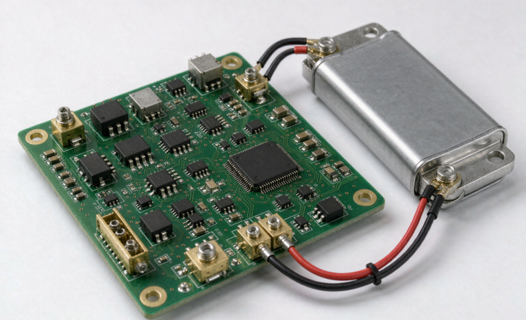
This is why the modern approach is condition-based monitoring rather than calendar-based replacement. The old VRLA practice of “replace every five years regardless” existed because the failure mode was stochastic and invisible. A properly specified BMS solution with remote telemetry gives you cell voltages, temperatures, and internal resistance continuously, which turns maintenance into trend analysis instead of guesswork.
The trap I see most often is teams porting the VRLA schedule across unchanged: annual 100%-depth discharges, fixed-calendar replacement, impedance logs nobody plots. That was built for a chemistry whose failure mode was grid corrosion and dry-out — not one whose aging is driven by solid-electrolyte interphase (SEI) growth on a hard carbon anode.
What Sodium Ion Chemistry Changes on the Maintenance Sheet
Let me be concrete about the four things that actually differ when the sticker on the module says Na-ion instead of LiFePO4.
1. The operating window is wider and sits lower
Typical production layered-oxide / hard-carbon Na-ion cells run roughly 1.5 V to 3.9 V per cell, against about 2.5 V to 3.65 V for an LFP battery. Two consequences follow. You cannot reuse a lithium charger or a lithium BMS calibration table — the voltage-to-SoC map is different and your technicians will misread state of charge if the display is not configured for Na-ion. And many Na-ion cells tolerate being taken to and stored at 0 V without the copper-dissolution damage that destroys an over-discharged lithium ion battery, which is a real logistics advantage for spares.
2. SoC estimation is harder, not easier
The hard carbon anode in almost every commercial sodium-ion battery has a long, flat low-voltage plateau and meaningful charge/discharge hysteresis. In plain terms, open-circuit voltage does not tell you state of charge as cleanly as it does on LFP or NCM, and coulomb counting drifts — so a BMS relying on OCV correction alone slowly walks away from truth, until a “100%” indication is really 80%.
The fix is procedural: schedule a periodic full-charge recalibration — a constant-voltage absorption phase held until tail current drops below the manufacturer threshold. I specify quarterly for standby fleets, monthly for anything seeing frequent shallow discharges. Log the date and absorbed amp-hours; that number trending upward at a fixed voltage hold is itself an early warning of rising internal resistance.
3. Low-temperature behavior is the standout
This is why my customers in northern climates and unheated telecom shelters look at Na-ion first. Current cells retain 85–90% of room-temperature capacity at -20 °C and accept charge where an LFP pack would need a heater blanket. For a site that sits at 0 °C for four months with no HVAC budget, that removes an entire subsystem — the self-heating circuit — with its failure modes and parasitic load.
Do not over-read it: cold charge acceptance is still derated and plating risk never reaches zero. Specify reduced charge current below 0 °C, and run the annual test at the site’s actual worst-case temperature at least once rather than always in a comfortable 22 °C room.
4. Energy density means you will be touching more modules
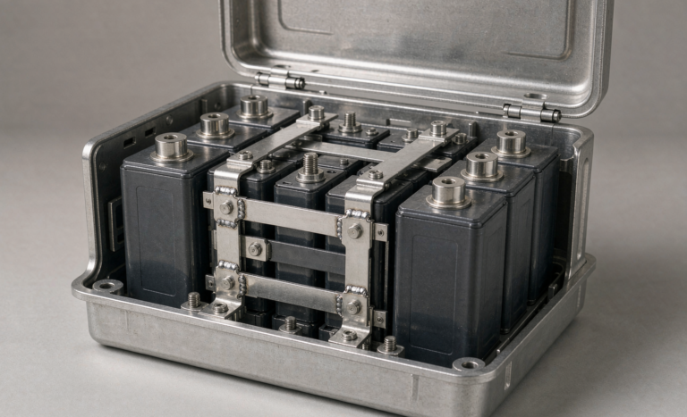
Production Na-ion cells land in roughly the 120–160 Wh/kg band at cell level, typically 15–25% below a comparable LFP cell. For stationary backup that rarely matters, but it can mean one more module per string for a like-for-like replacement — so your battery pack design review should confirm the rack, busbar, and fusing ratings still hold.
The Schedule I Actually Recommend
Here is the cadence my team writes into maintenance contracts for a sodium ion battery in standby service. Frequencies assume a typical commercial or industrial site with remote telemetry: harsh environments get compressed, unmanned huts get relaxed visual checks but tighter telemetry thresholds.
Monthly (15–30 minutes per site, can be remote)
- Pull the BMS log and confirm cell voltages are within the manufacturer’s spread limit. On a healthy resting pack I expect under 30–50 mV; above 100 mV at rest gets a work order.
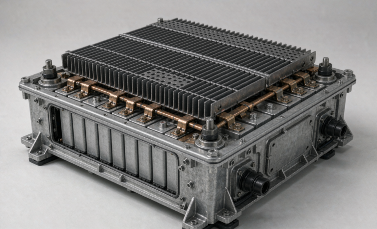
- Check maximum and minimum module temperatures and the delta between them. A module running 8–10 °C hotter than its neighbours at rest usually means an obstructed cooling path, a loose sense lead, or an internal fault.
- Verify standby SoC has not drifted below the autonomy requirement. If the BMS holds 100% by trickle top-up, confirm the float voltage is correct for the chemistry.
- Confirm telemetry is actually arriving — you would be surprised how many “battery failures” turn out to be a dead monitoring gateway.
Quarterly (1–2 hours on site)
- Controlled discharge test, typically to 80% depth or the site’s required autonomy, whichever is shallower. Record voltage sag per module, not just pack voltage.
- Measure DC internal resistance using a consistent method — same SoC, same temperature band, same pulse duration. Consistency matters more than absolute accuracy, because you are building a trend line.
- Full-charge recalibration; log the absorbed amp-hours.
- Thermal scan all busbar joints, terminal lugs, and breaker connections under load. Any connection more than 15 °C above an adjacent comparable connection at the same current is a defect.
- Visual inspection: swelling, vent deformation, electrolyte odor, condensation, enclosure corrosion, rodent damage, dust on intake filters.
Annually (half a day to a full day)
- Full-capacity verification discharge to the end-of-discharge voltage, per the manufacturer’s procedure and within the site’s risk tolerance. This is the number that goes into capital planning.
- Retorque all power connections to the manufacturer’s specified value with a calibrated torque wrench. Aluminum and copper both creep; a joint that was perfect at commissioning is not perfect three years later.
- Calibration check on BMS voltage and temperature sensing against a reference instrument. Sensor drift of 20–30 mV is more common than people expect, and it corrupts every decision made off that data.
- Insulation resistance and ground-fault testing, using only the method the manufacturer approves for that topology.
- Review firmware and security posture: patch level, network segmentation, and change the default BMS credentials. In every enterprise security review I have sat through in the last two years, unmodified default passwords on a networked battery system has been a finding.
- Update the spare-parts plan against observed fade, not the commissioning-day assumption.
The Four Measurements That Matter, and What the Numbers Mean
Maintenance programs fail because they collect data nobody interprets. Here is how I read the four signals that predict almost everything.
Cell voltage spread at rest. Under 50 mV is healthy, 50–100 mV is a trend watch, and above 100 mV — or any cell moving more than 20% from the pack mean across two consecutive reads — is a work order. Spread that appears only under load points to resistance (connection or cell DCIR), not capacity.
DC internal resistance. Baseline it within the first 90 days, then act when a cell exceeds 20–25% above its own baseline or 25% above the pack mean. Na-ion DCIR runs higher than LFP at the same temperature, which surprises technicians used to lithium numbers — do not “fix” a normal Na-ion reading because it looks wrong against a lithium reference card (see sodium ion battery vs lithium for the underlying chemistry differences).
Temperature. Calendar aging roughly doubles for every 10 °C above about 25 °C; that single relationship justifies most battery-room HVAC spend. Target 20–25 °C, alarm at 40 °C, and watch the spread across the pack — a 10 °C delta usually means an airflow problem you can fix for free.
Capacity trend. Plot delivered amp-hours at a fixed rate and reference temperature every quarter. Linear 2–3% annual fade is normal and boring; a knee — fade accelerating to 5–6% per year — is your replacement-planning trigger, and it typically appears 12–18 months before the pack reaches an 80% end-of-life threshold. That lead time is the entire value of this work.
Failure Signatures I Have Learned to Recognize
Some of these came from teardowns, some from post-mortems on sites that lost autonomy, and at least one from a mistake I made early on.
- Voltage sag that worsens only at high rate. Connection resistance or rising DCIR, not capacity loss. Find it with a thermal scan under load.
- Capacity that recovers after a recalibration. Not a battery problem — a state-of-charge estimation problem. Fix the recalibration interval.
- A module that runs hot at rest with no load. Internal micro-short or a balancing resistor stuck on. Pull it before it becomes a thermal event.
- Intermittent telemetry dropouts on one module. Usually a connector or lead, not the cell — though a failing cell can brown out its own slave board, so confirm it.
- Condensation after a discharge test. Cold pack, humid room, no heater. A site design defect that will eventually cause a ground fault, and far cheaper to fix with an anti-condensation heater than a new module.
Spare Parts and the Storage Question
Hold roughly one spare module per cabinet, or about 5% of the fleet, whichever is larger. Two rules get broken. First, store spares at 30–50% SoC in a 10–25 °C dry space and inspect every six months — a spare held at 100% SoC ages faster on the shelf than it would have in service. Second, never drop a fresh spare straight into a partially discharged string: bring it within 5–10% SoC of the string and confirm its DCIR is within 20–25% of the string mean, or the balancing circuit will spend weeks fixing what twenty minutes on a bench charger would have prevented. On the plus side, Na-ion’s tolerance of 0 V storage means a discharged spare is not automatically scrap.
Documentation You Will Be Asked For
Backup power sits under emergency systems codes, and the paperwork is not optional. Keep a site binder with the following and expect to produce it during an AHJ review or insurance audit:
- UN38.3 test summary for the cells or battery, plus transport classification and dangerous-goods documentation for any module movement.
- Cell and pack safety certification — typically IEC 62133 for the small-format cells in BMS and monitoring gear; for stationary industrial packs, IEC 62660-2/-3 or IEC 63056 depending on design, plus UL 1973 in North American projects.
- UL 9540A thermal runaway propagation data where the installation falls under NFPA 855 or a fire code referencing it.
- Commissioning records: baseline DCIR, baseline capacity, torque values, as-built single-line.
- Maintenance logs with trend charts, not pass/fail tick sheets. When an inspector asks how you know the battery will carry the load, the trend is the answer.
The Bottom Line
Sodium ion is a good fit for backup sites that are cold, remote, cost-sensitive, or tired of replacing VRLA strings on a calendar. It is not maintenance-free, and any vendor who says otherwise has not maintained a fleet. What it offers is better instrumentation, more forgiving storage and transport behavior, and a wider low-temperature envelope — which together make a condition-based program easier to run than the one you are running on lead-acid today. One caveat: if your site has constraints a standard module cannot absorb — a legacy UPS whose float voltage will not suit the chemistry, sustained ambient above 40 °C, seismic or marine classification, or a DCIM protocol your BMS cannot close the loop with — that is a custom battery solution conversation for specification time, not a maintenance problem to fix later.
If you are writing the maintenance specification for a new site, spend your effort in three places: the recalibration interval (Na-ion SoC estimation is harder), the thermal environment (10 °C is worth years of life), and trend logging (the trend is the only thing that gives you lead time). Everything else is detail.
Frequently Asked Questions
How often does a sodium-ion backup battery need a full discharge test?
Annually for full-capacity verification, with a shallower 80%-depth or autonomy-duration test each quarter. That matches the philosophy behind emergency power supply codes such as NFPA 110, which care that you prove the system carries the load, not how deeply you discharge it. Never run a full discharge on a live critical load without a verified alternate source.
Can I use my existing lithium-ion charger or BMS settings?
No. The voltage window differs (roughly 1.5–3.9 V per cell versus 2.5–3.65 V for LFP), as does the OCV-to-SoC relationship, because of the hard carbon anode’s flat plateau and hysteresis. A BMS configured for lithium will misreport state of charge and may trip on thresholds that are wrong for the chemistry. Confirm the charger profile and BMS calibration table are Na-ion specific before energizing.
What is the realistic service life in standby duty?
Production cells are commonly specified at 3,000–6,000 cycles to 80% capacity, but in standby duty your limiting factor is calendar aging, not cycling. In a well-kept 20–25 °C room I would plan for a 12–15 year window — and re-baseline that estimate against your own observed fade curve after year three rather than trusting the datasheet.
Does sodium-ion really work at -20 °C without heating?
Current cells retain 85–90% of room-temperature capacity at -20 °C and accept charge where LFP would require heating — a real advantage for unheated shelters. It is not unlimited: charge current must still be derated in the cold, and your worst-case commissioning test should run at the site’s actual minimum temperature at least once.
Can I mix sodium-ion modules into an existing lithium string?
No. Different voltage windows, SoC behavior, and charge acceptance mean a mixed string cannot be balanced safely or predicted usefully. Trial Na-ion on a separate string or site, and keep the maintenance records separate so your trend data stays clean.
Is a sodium-ion battery safe to ship or store fully discharged?
Many Na-ion cells tolerate discharge to 0 V and storage at that state — a meaningful logistics advantage over lithium-ion, where deep over-discharge causes copper dissolution and permanent damage. Transport is still a dangerous-goods operation and UN38.3 still applies; always recharge and capacity-check the module before placing it in service.
What is the single most common maintenance mistake?
Skipping the charge recalibration. Because Na-ion state-of-charge estimation drifts, a pack that has not recalibrated for a year can indicate full while holding materially less energy — and you find out during the one event that mattered. Put it on the calendar and log the absorbed amp-hours every time. The close second is treating temperature as a comfort issue: aging roughly doubles for every 10 °C above 25 °C, so holding the room at 20–25 °C with clean airflow returns more life than almost anything else here.