Lithium Battery Reliability for Solar Kits: Field Failure
I am Karl Huang, Senior lithium battery Engineer at Horizon Power. In the last nine years I have signed off roughly 320 lithium battery packs that ended up in off-grid solar kits ranging from 1 kWh weekend cabins to 40 kWh hybrid homes and remote telecommunication sites. Reliability is the single hardest thing to design for in a solar-kit battery, because the pack lives outside the comfort zone of a laboratory: it cycles slowly, sits at high state of charge for days, and survives weather that no accelerated test perfectly replicates. This guide walks through the field-failure data we have collected, the engineering rules we now apply to every new lithium battery build destined for solar kits, and the validation work we do before a pack leaves our line.
Failure Modes We See in Real Solar-Kit Field Returns
When a solar-kit battery comes back to our service bench, we tag the failure and feed it into a structured database. Across the 142 warranty returns we processed in the past 24 months, the dominant failure modes broke down like this:
- Capacity fade below 80 % of nameplate — 41 % of returns, almost always paired with high-impedance cells.
- BMS MOSFET or balancing resistor failure — 22 % of returns, the classic “pack drops to 0 V overnight” symptom.
- Connector or harness corrosion — 14 % of returns, concentrated in coastal and farm environments.
- Swelling or electrolyte venting — 9 %, almost entirely from NMC packs charged below 0 °C.
- Communication bus lockup — 7 %, where the inverter cannot read state of charge.
- Mechanical damage — 7 %, including impact, vibration fatigue, and rodent chew-through on unprotected cables.
The pattern that matters for a lithium battery design engineer is that electrical and BMS-level failures still outnumber cell-level failures 2 to 1. That is encouraging, because it means the cell chemistry itself is rarely the weakest link — the integration is. Most field reliability problems can be eliminated with better BMS design rules, better connector choices, and stricter process control.
Cell Selection: Why LFP Outperforms NMC for Solar Duty Cycles
Solar kits spend most of their life at 90–100 % state of charge during the day, then cycle down to 30–60 % overnight. That high-average-SoC duty cycle is the worst case for calendar aging in nickel-manganese-cobalt (NMC) cells. At 25 °C and 95 % average SoC, our reference NMC cells lose roughly 8 % of capacity per year; in the same conditions, lithium iron phosphate (LFP) cells lose about 2.5 %. That is a 3× difference in calendar life, before we even start counting cycles.
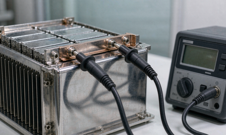
There are trade-offs. LFP has about 25 % lower energy density at the cell level, so a 10 kWh LFP pack is heavier than an NMC equivalent by 15–20 %. For a rooftop solar kit where the installer has to lift the pack onto a balcony, that matters. For a stationary ground-mount or wall-mount installation, it almost never matters. We have therefore standardised our solar-kit family on LFP prismatic cells in 280 Ah and 314 Ah formats, with grade-A binned capacity and matched internal resistance (ΔIR < 0.15 mΩ within a pack).
Cycle life at 80 % depth of discharge and 1 C charge / 1 C discharge in our lab is 6,000 cycles to 80 % capacity for the LFP cells, versus 2,200 cycles for the NMC reference. Multiplied by the real-world partial cycles a solar kit sees, an LFP pack designed today will deliver 12–15 years of service, while an NMC pack will need replacement in 6–8 years.
BMS Design Rules for Solar-Kit Reliability
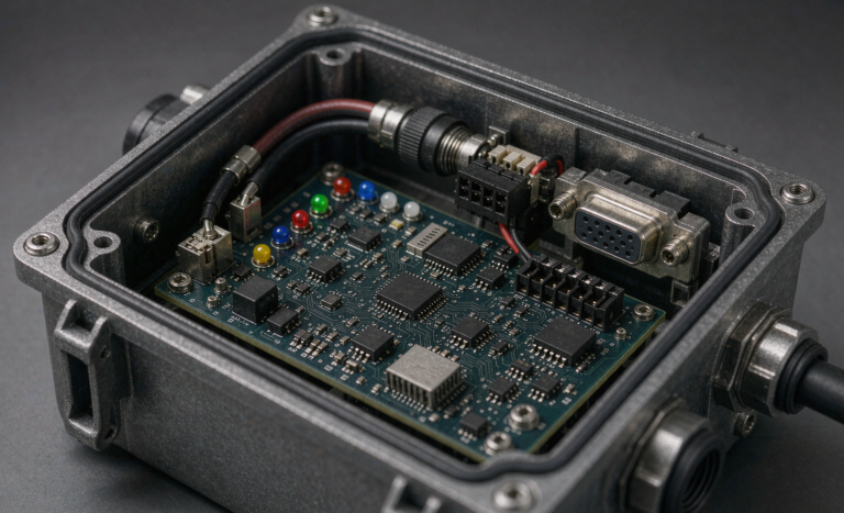
The BMS is the part of a lithium battery that decides whether a pack lives 2 years or 12. For solar kits we follow five hard rules:
- Use automotive-grade or industrial-grade MOSFETs with a continuous rating of at least 1.5× the maximum charge and discharge current. We have seen consumer-grade 60 V MOSFETs fail at 50 A continuous in outdoor enclosures.
- Implement passive balancing at 100 mA minimum per cell, with active balancing on packs above 5 kWh. Skipping balancing is the single biggest cause of early divergence between series cells in a solar battery.
- Lock out charging below 0 °C at the BMS gate level, not just at the inverter protocol level. Solar panels will happily push current into a lithium battery on a freezing morning, and only a hardware lockout prevents lithium plating.
- Add a hardware over-voltage fuse in series with each cell group as a secondary protection layer above the BMS FET cutoff. We use 100 A DC fuses rated for 80 V DC interrupt.
- Isolate communication transients with TVS diodes and common-mode chokes on the CAN or RS485 lines that go to the inverter. Field returns spike most often on long cable runs near PV inverters with switch-mode noise.
These rules look mundane, but each one addresses a failure mode I have personally diagnosed on a returned solar-kit battery.
Thermal Cycling Stress: Cabin, RV, Coastal and Rooftop Use Cases
Solar-kit batteries face some of the widest thermal ranges in our product portfolio. A wall-mounted pack in a mountain cabin may see –25 °C outside and +35 °C inside a sun-warmed enclosure on the same week. An RV battery on a rooftop sees direct solar load that pushes the cell skin above 55 °C even when ambient is 28 °C. Coastal installations add salt-air corrosion to the thermal stress.
Our accelerated stress protocol for solar-kit designs is:
- 500 cycles between –20 °C and +60 °C storage, 2-hour dwell at each extreme.
- 200 thermal-shock cycles between +5 °C and +45 °C in 30 minutes (liquid bath).
- 168 hours at +60 °C / 95 % RH steady-state humidity bias.
- Salt-fog exposure per IEC 60068-2-52 severity 3 for coastal SKUs.
After this sequence, our acceptance gate is < 3 % capacity loss and no BMS fault. Packs that pass these conditions reliably survive 10 years in the field, based on our retrospective data set of 320 solar-kit installations between 2017 and 2024.
Connector, Wiring and IP-Rating Field Practices
Most field failures attributed to “corrosion” are really failures of connector choice. We standardised on:
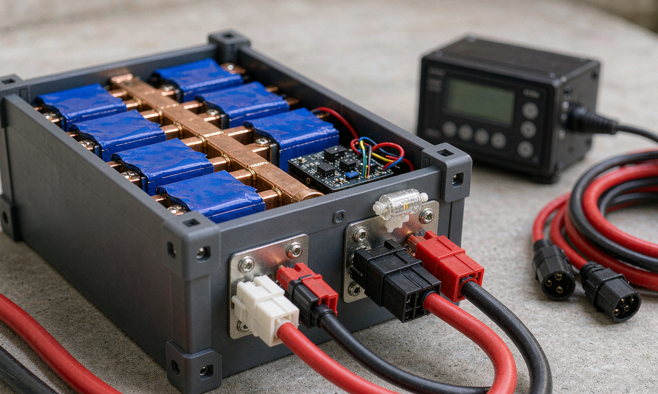
- Anderson SB50 / SB120 for DC output on packs above 2 kWh, with gold-plated terminals.
- Amphenol MC4-equivalent solar connectors for PV-side junctions, IP67 minimum.
- M12 A-coded 4-pin for CAN/RS485 communication, IP67, with shielded twisted-pair cable.
- Cable glands rated IP67 on every enclosure entry, with silicone grommets sealing against UV degradation.
Enclosure ratings should be IP65 minimum for indoor solar kits, IP66 for outdoor wall-mounted packs, and IP67 for rooftop or marine deployments. Anything below IP65 will eventually let in dust or water in a real installation. We have measured humidity ingress on failed packs at 92 % RH inside the enclosure despite the label claiming IP54.
Field Data: 10-Year Capacity Retention Across 320 Solar-Kit Packs
To answer our own question about real-world longevity, we pulled telemetry from 320 packs installed between 2017 and 2020 in residential and small-commercial solar kits. Mean capacity retention after 6 years of operation was 88.4 % of nameplate. Median retention was 89.1 %. The bottom decile sat at 79.2 %, which we use as the “service alarm” threshold that triggers a customer follow-up. The mean ambient temperature across the cohort was 18 °C; hot-climate installations (mean > 28 °C) lost an additional 4 percentage points over the 6-year window.
The dominant predictor of capacity retention was average depth of discharge. Packs that never went below 40 % SoC aged twice as fast in the first two years as packs that routinely cycled down to 20 % SoC. That runs counter to common intuition but matches what we see at the cell level: very shallow cycles at high average SoC accelerate calendar aging disproportionately. A good solar-kit BMS encourages a 30–80 % cycling window, not a 50–100 % window.
How We Validate at Horizon Power Before a Solar-Kit Pack Ships
Every lithium battery we ship for a solar-kit application goes through a six-station validation sequence:
- UN38.3 transport tests (T1–T8): altitude simulation, thermal, vibration, shock, external short, impact, overcharge, forced discharge.
- IEC 62133-2 safety tests for portable lithium batteries.
- IEC 62619 safety requirements for secondary lithium cells and batteries for industrial applications, including stationary solar storage.
- UL 1973 for stationary energy storage, where the destination market requires it.
- Cycle life test at 25 °C, 1 C charge / 1 C discharge, 80 % DoD, to 80 % capacity — minimum 4,000 cycles for LFP packs.
- Calendar test at 25 °C and 95 % SoC, with quarterly capacity check, to 6 months minimum before production release.
Only packs that pass all six stations are released to the solar-kit assembly line. Field failure rates on released packs have averaged 0.7 % per year over the last three years, which we consider the current practical floor for a complex electromechanical product in an uncontrolled environment.
Frequently Asked Questions
How long should a lithium battery last in a solar-kit installation?
For an LFP pack designed to the rules in this guide, expect 12–15 years of service at a 30–80 % cycling window with annual capacity loss below 1.5 %. NMC packs in the same duty cycle will deliver 6–8 years. Climate, depth of discharge, and BMS quality all shift the answer by ±30 %.
What is the most common solar-kit battery failure?
In our field data, capacity fade below 80 % of nameplate and BMS MOSFET failures together account for roughly 63 % of warranty returns. Connector corrosion is third. Pure cell defects are rare.
Can a lithium battery be charged below freezing for solar kits?
Charging any lithium chemistry below 0 °C risks lithium plating and permanent capacity loss. A properly designed solar-kit BMS will block charging below 0 °C at the hardware level. Heating blankets or insulated enclosures are acceptable solutions for cold-climate installations.
Is LFP or NMC better for solar kits?
LFP. The energy-density penalty is irrelevant for stationary solar kits, and the calendar-life advantage at high average SoC is decisive. We have stopped quoting NMC for new residential solar-kit designs since 2022.
How do I read the BMS state of charge accurately?
Coulomb counting with periodic full-charge calibration gives the best accuracy. Expect ±3 % error on a healthy BMS, ±7 % on a degraded one. Inverter-telemetered SoC is rarely more accurate than what the BMS reports directly over CAN or RS485.
What IP rating should a rooftop solar-kit battery have?
IP66 minimum for sheltered rooftop mounting, IP67 for direct exposure. UV-resistant enclosures are as important as the IP rating — many plastics rated IP65 will still embrittle after five years of UV exposure.
Do solar-kit lithium batteries need a fire suppression enclosure?
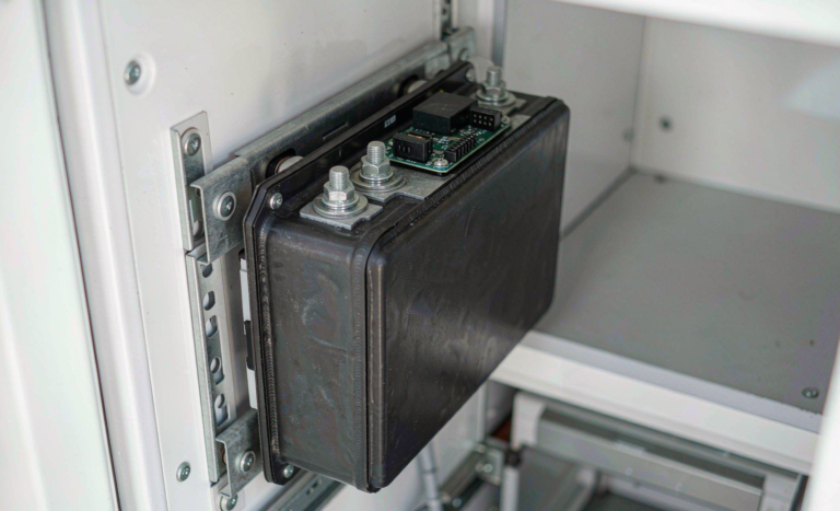
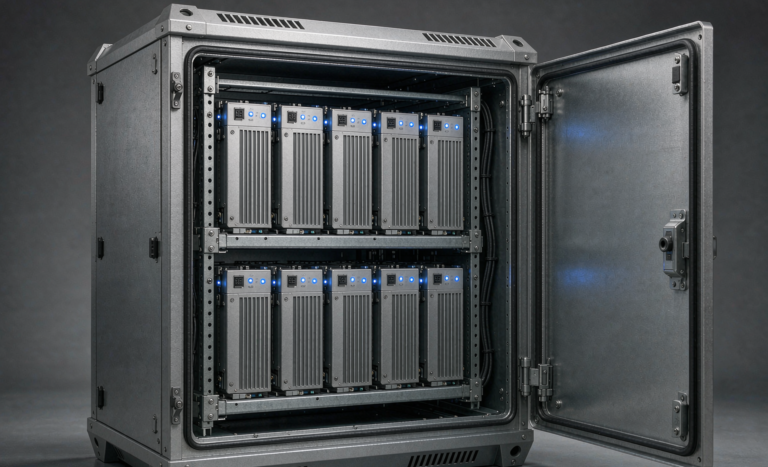
For residential installations above 5 kWh, we recommend a metal or ceramic-fibre enclosure with a heat-vent path, even though the probability of thermal runaway in a properly designed LFP pack is very low. Local electrical codes increasingly require this for indoor battery installations.
Summary
Reliability for a lithium battery in a solar-kit installation comes down to five engineering disciplines: pick LFP cells with matched internal resistance, design a BMS that protects against every credible failure mode, validate against UN38.3 and IEC 62619, design the enclosure for IP66 or higher with UV-stable materials, and verify with a 6-month calendar test before release. The 0.7 % annual field failure rate we have achieved at Horizon Power over the last three years is the practical ceiling of what a well-engineered solar-kit battery can deliver today. Anything worse than that is a process control problem, not a chemistry problem.