Home Energy Storage Design for Farms: Dust-Proof
Why Farm Energy Storage Is a Different Engineering Problem
Most residential battery guides are written for suburban homes with clean garages, stable grid power, and modest loads. A farm is none of those things. Over the past eleven years designing home energy storage systems for agricultural customers, I have learned that a farm is closer to a small industrial site than a house: dust from grain handling and gravel roads, ammonia and humidity inside barns, voltage sags from irrigation pumps starting across the line, and loads — well pumps, milk coolers, ventilation fans, heat lamps — that cannot tolerate an outage the way a living-room lamp can. When I approach a home energy storage design for a farm property, I start from the load profile and the environment, not from a catalog brochure.
This article walks through how we engineer farm storage systems in practice: load profiling for agricultural duty cycles, enclosure and ingress protection choices, sizing for well-pump and critical-load backup, inverter and generator integration, and the compliance standards (UL 9540, UL 1973, NEC 706) that separate a defensible installation from a liability. My goal is to give farm owners, installers, and OEM buyers enough engineering substance to evaluate any proposal on its merits.
Step One: Profiling Real Agricultural Loads
The single most common sizing mistake I see is treating a farm like a house with a bigger bill. The daily kWh number may look similar, but the shape of the load is completely different. A suburban home has a morning and evening peak with a gentle overnight floor. A dairy or crop farm has motor-driven loads that start hard, run in cycles, and in some cases run around the clock.
When we do a load study, I ask for three data sources: twelve months of utility bills (to get seasonal totals), a one-week logging run with a CT clamp on the main service (to get the actual shape), and a written list of loads the owner considers critical during an outage. The logging run matters because nameplate data lies. A 1.5 kW well pump can draw 6–9 kW inrush for 300–800 ms at startup. A 5 hp irrigation motor across-the-line can pull 30+ kW momentarily. If the inverter and battery cannot supply that surge, the system will nuisance-trip the first time a pump kicks in, and the owner will lose confidence in the entire investment.
We classify every load into three tiers:
- Tier 1 — life and livestock safety: well pump, water pressure system, ventilation fans for enclosed livestock, milk cooling, medical or heating circuits for young animals. These get unconditional backup.
- Tier 2 — economic continuity: refrigerated storage, freezers, shop circuits, security and gate systems. Backup as capacity allows.
- Tier 3 — deferrable: shop tools, grain augers, EV charging, comfort loads. These are shed first and become the flexible layer for solar arbitrage.
For a typical mixed farm (one dwelling, one well pump, two chest freezers, barn lighting and fans), I usually see a Tier 1 + Tier 2 continuous load of 2–4 kW with peaks to 8–10 kW including a heat pump or the well pump cycling. That number, not the 40 kWh/day the whole property consumes, drives the battery bank sizing. A useful rule we apply: size the battery for the critical load energy over the expected outage duration, then check surge capability against the single largest motor start with 25% headroom.
Step Two: Sizing the Battery for Well-Pump Backup Runtime
On nearly every farm I have worked with, the well pump is the load that defines the system. No water means no livestock watering, no sanitation, no fire suppression margin. So the question I get most often is: how long can the battery run the well pump during an outage?
The honest engineering answer is that a well pump does not run continuously — it runs to refill a pressure tank, then stops. A typical residential well pump (0.75–1.5 kW) cycles 15–40 times per day in normal use, with each cycle drawing 0.3–1.5 kWh depending on drawdown depth and tank size. If we suppress non-essential water use during an outage, the daily well-pump energy drops to roughly 1.5–3 kWh.
Combine that with Tier 1 baseline loads — say 0.8 kW average for refrigerator, freezers, lighting, and fans — and a 10 kWh usable battery bank supports roughly 24–30 hours of outage. Add a 15 kWh bank and you are comfortably past 36 hours with conservative water use. I published a longer treatment of this in our guide to home energy storage runtime planning, and the same math holds: specify usable capacity (not nameplate), assume 90% inverter efficiency, and never plan to cycle below 10–15% state of charge in backup scenarios.
Surge capability deserves its own paragraph. A 1.5 kW pump with 6× inrush needs the inverter-plus-battery combination to deliver 9 kW for half a second without collapsing the DC bus. With LiFePO4 cells at 50% state of charge and a cold morning, internal resistance rises — I have measured a 20–30% increase in IR at 0°C versus 25°C on the same cell. That is why we specify battery banks whose continuous discharge rating is at least 1.5× the pump start demand, and why the BMS current limit must be verified against the surge, not just the steady-state load. A 100 A BMS on a 48 V bank caps continuous output near 5 kW; if your pump start needs 9 kW through a 48 V bus, you need a 250 A-class path or a soft-start kit on the pump.
Step Three: Enclosures, Ingress Protection, and the Farm Environment
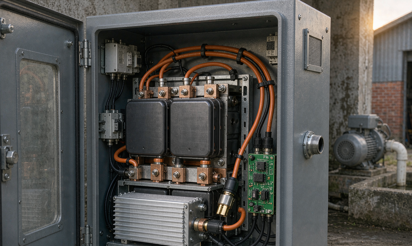
Farm air is hostile to electronics. Grain dust is abrasive and slightly conductive when humid; ammonia from livestock operations corrodes copper traces and connector plating; rodent traffic chews insulation. I have opened failed farm installations and found dust cakes inside NEMA-1 enclosures that would have been prevented by a 200-dollar cabinet upgrade. The home energy storage design for a farm must treat ingress protection as a first-order requirement, not an accessory.
Our standard specification ladder looks like this:
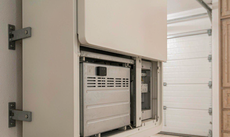
- Indoor installation in a conditioned utility space: the battery’s own IP20–IP21 module enclosure is fine, but we still specify a sealed cabinet if the space shares air with a barn or workshop.
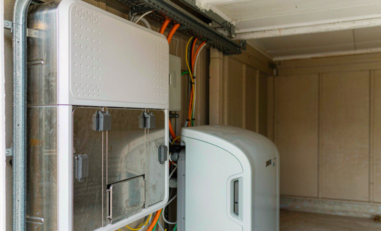
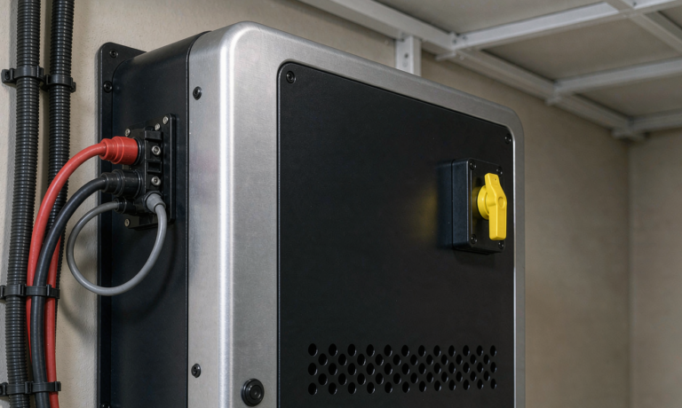
- Unconditioned barn, shed, or equipment room: IP54 minimum for the battery system, with filtered convection or active cooling, and conduit entries sealed with gland fittings rather than knockout plugs.
- Outdoor wall or pad mount: IP65 enclosure, UV-stable powder coat, operating range verified to −20°C or lower with self-heating, and shading from direct afternoon sun in hot climates.
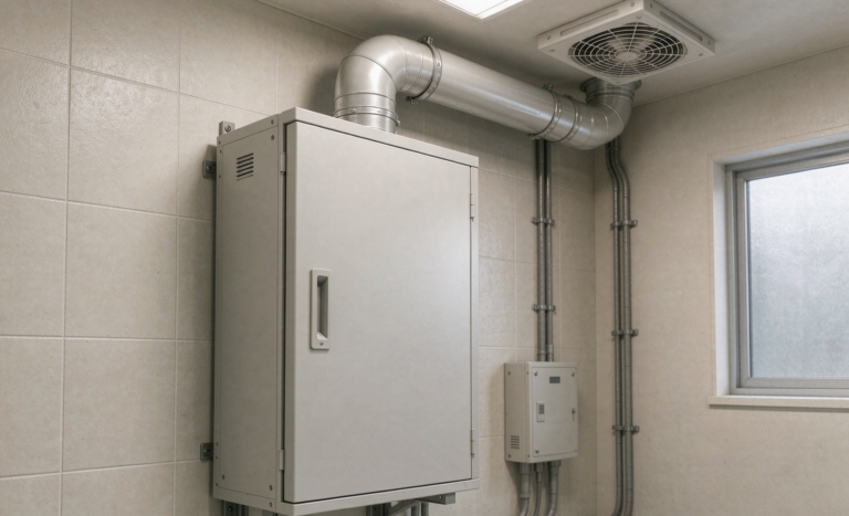
Temperature is the quiet killer. LiFePO4 chemistry tolerates heat far better than NMC, but charging below 0°C causes lithium plating unless the pack has a heating system or the BMS blocks charge until cells warm. On outdoor farm installations in cold regions, I specify packs with integrated heater pads and a BMS that enforces the 0°C charge floor — a feature we treat as mandatory, not optional, in any custom battery solution we ship into northern climates. Ventilation louvers must carry fine mesh dust filters that the owner can actually remove and rinse; a louver that cannot be serviced becomes a solid wall of chaff within two seasons.
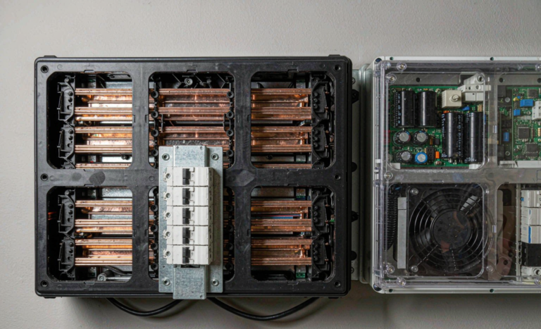
Compliance frameworks matter here too. UL 9540 is the system-level certification for energy storage systems in North America, and it evaluates the battery, inverter, and enclosure as an integrated unit. UL 1973 covers the battery itself for stationary applications. NEC Article 706 (Energy Storage Systems) governs the installation: disconnecting means, labeling, conduit separation, and working clearances. When a farm owner asks me to review a quote, the first three things I look for are UL 9540 listing on the complete system, a UL 1973 or UL 2580 cell/pack report, and an installation plan that references NEC 706. Absence of any of the three is a red flag regardless of price.
Step Four: Inverter Pairing, Generator Integration, and Solar Arithmetic
A farm storage system is rarely standalone — it lives alongside a solar array, a standby generator, or both, and the control logic between them is where most integration pain concentrates.
Inverter sizing. We size the hybrid inverter to the largest simultaneous Tier 1/Tier 2 load plus motor surge, which on most farms lands at 8–10 kW continuous with 2× surge headroom for 5–10 seconds. If an irrigation pump will ever run on the backup path, we either add a soft-starter to the pump or move the pump to the grid-only/non-backup panel. I would rather make that architectural decision on paper than discover it during the first outage.
Generator integration. Many farms already own a PTO or diesel generator. The cleanest design treats the generator as a bulk recharge source, not a load server: during a multi-day outage, the generator runs at 60–80% load (its efficiency sweet spot) for 1–2 hours to recharge the battery, then shuts down while the battery carries the load silently. This “generator as charger” architecture cuts fuel consumption by 50–70% versus running the generator continuously, eliminates the low-load wet-stacking problem, and lets the battery handle pump surges that would otherwise flicker the generator’s voltage. The inverter must support AC-coupled generator input with a start signal — a feature worth specifying explicitly.
Solar arithmetic. Solar on a farm is usually not land-constrained, which changes the economics. Rather than oversizing the battery to ride through multi-day clouds, it is often cheaper to add 2–4 kW of panels and a moderately sized battery. In winter at 45°N latitude, a fixed array produces roughly 2–2.5 kWh per installed kW on a clear December day; the panel count, not the battery, is what restores that number after a storm. I walk through the full math in our article on solar battery storage sizing for rural properties, but the summary is: battery covers 1–2 days of critical load, solar plus generator covers everything beyond that.
Step Five: Cell Chemistry, BMS Design, and Service Life
For farm duty, LiFePO4 is my default recommendation, and the reasons are practical rather than fashionable. LFP delivers 4,000–6,000 cycles to 80% depth of discharge in credible test data, it does not enter thermal runaway as readily as high-nickel NMC under abuse testing, and its flat voltage curve keeps inverter electronics happy across the state-of-charge window. For a system cycling daily for 15 years, the cycle-life difference between LFP and NMC outweighs NMC’s energy-density advantage in almost every stationary case — and on a farm, floor space is rarely the constraint.
Inside the pack, I care about three BMS behaviors that farm conditions stress especially hard:
- Balancing strategy: passive balancing at a few hundred milliamps is adequate if cells are matched at the factory (we specify ≤25 mV initial spread), but top balancing during commissioning is non-negotiable after transport and storage.
- Charge-block at low temperature: the BMS must refuse charge below 0°C cell temperature and log the event; silent refusal is better than a plating failure that shows up two winters later as capacity fade.
- Current limiting and short-circuit response: farm outages tempt owners to add loads beyond design. A BMS with a firm, documented current limit — plus a labeled “backup loads only” panel — protects the system from well-meaning improvisation.
Transport and acceptance are part of the design too. Every pack we ship travels under UN 38.3 (the mandatory transport test series for lithium cells and batteries), and we ask installers to verify cell-voltage spread and state of charge on delivery before energizing. IEC 62133-2 provides the cell-level safety baseline for smaller packs; for larger stationary systems, UL 1973 and UL 9540A thermal-runaway test reports give the fire-service-recognized evidence that a cell failure will not propagate. These documents are not paperwork — they are the distillation of the failure modes that kill systems in the field.
Commissioning, Monitoring, and Maintenance on a Working Farm
A storage system on a farm will be ignored for months at a time, so the commissioning and monitoring design must assume inattention. During commissioning I insist on: a recorded capacity test at rated current to confirm nameplate usable energy within 5%; a pump-start surge test observed on the inverter event log; verification of generator auto-start and recharge behavior; and a walkthrough with the owner covering what each indicator means and what they should never touch.
For monitoring, I prefer systems that log cell-level data and push it to the cloud, with alerts configured for three conditions specifically: a cell-voltage spread growing beyond 80–100 mV (early imbalance or a failing cell), sustained operation above 90% or below 15% state of charge (misconfigured load priority), and any temperature-charge-block events in winter (heater or sensor fault). Catching imbalance at 100 mV costs a service visit; catching it at 400 mV usually costs a module.
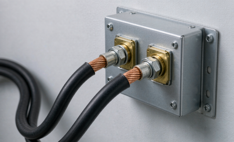
Annual maintenance on a farm system is modest: rinse the enclosure dust filters, torque-check DC terminations (thermal cycling works connections loose — I have fixed two “failed” farm systems that were just a loose busbar bolt), inspect conduit penetrations for rodent damage, and download the event log for review. None of this requires the installer; a competent owner with a checklist can do it, which matters when the nearest service technician is ninety minutes away.
A Worked Example: 12 kW Solar + 15 kWh Battery on a Mixed Dairy Farm
To make the numbers concrete, here is a recent design. The property: a 60-cow dairy with a dwelling, a 1.1 kW well pump, two milk-cooling tanks (2.4 kW combined when running), barn ventilation fans (1.5 kW), a chest freezer bank, and a workshop. The utility tariff had a demand charge that stung in summer.
The load study showed 38 kWh/day total consumption but only 9 kWh/day of Tier 1 + Tier 2 critical load. We proposed a 15 kWh LFP battery (usable ~13.5 kWh), an 10 kW hybrid inverter with 20 kW / 10-second surge rating, a 12 kW solar array, and AC coupling to the existing 12 kW PTO-generator-equipped tractor setup. Critical-load runtime on battery alone: 32–36 hours including normal well-pump cycling. With the solar array at even winter production (~20 kWh/day December average), the system rides through multi-day outages with the generator contributing at most 2 hours of runtime per day in the worst cloud cover.
The demand-charge shaving and self-consumption gains covered the battery premium in our model at year 6; the outage protection — milk spoilage alone was a 3,000-dollar loss event in the customer’s history — paid for the difference in avoided risk on the first avoided incident. That is the honest economic story of farm storage: the ROI is partly kilowatt-hours, but mostly the cost of the bad night you never have.
Common Design Mistakes I See in Farm Storage Proposals
Before the FAQ, a short list of failure patterns, because I keep seeing the same ones:
- Sizing on the utility bill instead of the load study. The bill includes augers and shop loads that will never be on the backup panel; the battery gets oversized, the inverter undersized for pump surge, or both.
- Ignoring inrush. Specifying a 5 kW inverter for a 4.5 kW steady-state load with a 1.5 kW pump on the backup panel is a nuisance-trip waiting to happen.
- NEMA-1 enclosures outdoors or in barns. Dust and ammonia win within two seasons.
- No low-temperature charge protection. Batteries installed in unheated sheds that silently lose capacity every winter from charging cold cells.
- No generator pathway. A battery sized for the grid’s reliability eventually meets the multi-day ice storm; without a recharge path, the system becomes a very heavy flashlight.
- Missing certifications. No UL 9540 system listing, no UN 38.3 transport documentation, no thermal-runaway test data. On a farm with wooden barns and livestock, this is not a formality.
FAQ: Farm Home Energy Storage Design Questions
How big should a battery be to back up a well pump on a farm?
Plan for 1.5–3 kWh/day of well-pump energy under conservation use, plus your other critical loads. In practice a 10 kWh usable bank supports about 24 hours and a 15 kWh bank about 36 hours for a typical farm critical-load profile. Always verify the inverter and battery can deliver the pump’s starting surge — for a 1.5 kW pump that is roughly 6–9 kW for half a second.
Can I put a lithium battery in an unheated barn?
Yes, if three conditions are met: the enclosure is at least IP54 against dust, the pack has integrated heating or a BMS that blocks charging below 0°C, and the continuous operating range covers your winter minimum. LiFePO4 discharges fine in cold weather; it is charging cold cells that causes permanent damage.
Is LiFePO4 the right chemistry for farm energy storage?
For most farm applications, yes. Its 4,000–6,000 cycle life suits daily cycling, its abuse tolerance suits unattended rural sites, and its weight is rarely a constraint in stationary enclosures. NMC makes sense where volume is critical; on a farm, it usually is not.
Do I still need a generator if I have a battery?
For multi-day winter outages, yes — but as a recharge source, not a continuous runner. A generator that runs 1–2 hours per day to recharge a 15 kWh battery consumes 50–70% less fuel than one running continuously, and the battery handles motor surges that would destabilize a lightly loaded generator.
What certifications should a farm battery system have?
UL 9540 for the complete system, UL 1973 for the battery, and UN 38.3 documentation for transport. Ask for UL 9540A thermal-runaway test data for fire-safety confidence, and make sure the installation plan references NEC Article 706. A proposal without these is a price signal, not a specification.
How often does a farm battery system need maintenance?
Annually: rinse dust filters, torque-check DC terminations, inspect conduit penetrations for rodent damage, and review the event log. Cell-level monitoring with spread and temperature alerts turns the rest into a remote check rather than a site visit.
Designing home energy storage for a farm comes down to respecting the environment and the motors. Get the load study right, protect the electronics from dust and cold, prove the surge path, and keep a recharge pathway for the long outage — do those four things, and the system will quietly do its job for fifteen years while everything else on the farm demands attention.