Semi-Solid State Battery Reliability for Aerospace: Prognostics Threshold Setting, Cell-Level Fault Isolation, and On-Orbit Telemetry Trending
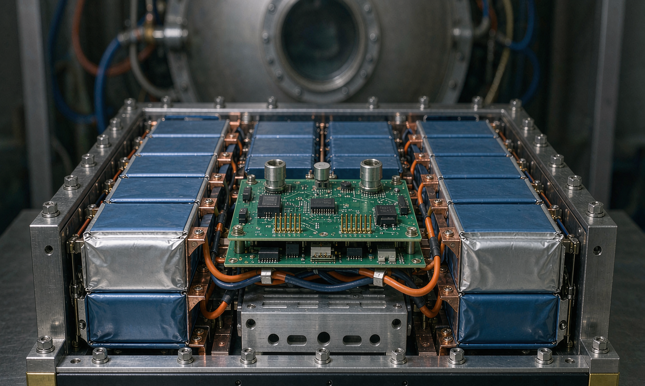
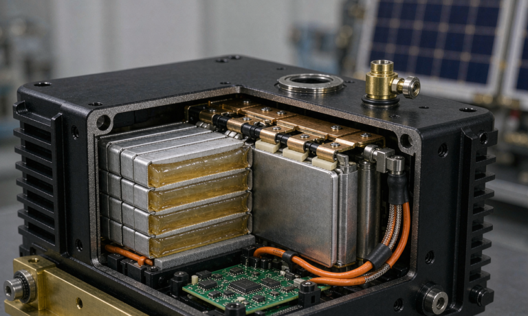
I have been signing off semi-solid state battery reliability for aerospace programs since the first HAPS demonstrator we flew in 2019, and I can tell you from the bench that a pack can be perfectly qualified on the ground and still be a poor performer once it reaches orbit. The reasons are not subtle. The reasons are what you choose to watch, how tight you set the trip lines, and whether a single failing cell can propagate a fault or simply get isolated while the bus keeps delivering. This article is the playbook I use when a customer asks me to defend a 10-year mission life with a semi-solid lithium chemistry and a LEO or HAPS duty cycle.
For the sake of this guide, I will treat the semi-solid state cell as a hybrid: a gel-polymer and ceramic-blend electrolyte that suppresses liquid leakage, but one that still carries enough free lithium-ion solvent to behave like a conventional Li-ion cell at high C-rate. If you read my earlier notes on drone battery duty envelopes and drone lithium battery thermal management, you will recognise the same flight-cycle vocabulary, just applied to a 3-axis stabilised bus instead of a quad rotor.
1. Why Reliability Metrics Diverge in LEO and HAPS
A semi-solid cell that delivers 4,000 cycles on a calendar-life cycler at 25 °C and 100% DoD will not deliver 4,000 cycles on a HAPS airframe at −40 °C cold soak and 35 °C solar soak. The reasons fall into three buckets, and I track them separately in the reliability model.
- Cycling asymmetry. A LEO satellite sees roughly 5,500 eclipse cycles per year. A HAPS airframe sees one day/night cycle per 24 hours but with deeper DoD. The accelerated test matrix must match the actual cycle, not the cycle you can afford to run.
- Calendar stress at vacuum. Outgassing of plasticiser and electrolyte solvent at <10−6 Torr raises the partial pressure of volatile organics around the cell stack. I have seen this deposit on cold plates and BMS ICs within the first 18 months, enough to skew thermistor readings by 0.8 to 1.4 °C if the BMS is not conformal-coated.
- Vibration and acoustic load. Launch acoustic and pyroshock load are not the same spectrum as in-orbit vibration. HAPS adds a continuous 2–4 gRMS rotor-induced spectrum on top of thermal cycling. We derate cycle life 35 to 50% for HAPS depending on how the pack is mounted.
If you fold all three into the reliability model, you land at roughly 1,800 to 2,500 equivalent full cycles for a 10-year LEO mission and 1,200 to 1,600 for a 10-year HAPS mission. The cell is the same. The envelope is not. That is the first thing I make sure the program office understands before any conversation about prognostics thresholds starts.
2. Cell-Level Fault Isolation in a Semi-Solid Pack
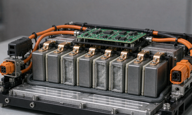
Single-cell thermal runaway is the failure mode everyone in this industry plans for, and the difference between a recoverable anomaly and a loss-of-mission is almost always whether the failing cell could be electrically isolated. With a semi-solid state cell, the polymer-ceramic blend helps a lot. The dendrite growth that triggers internal shorts in liquid-electrolyte cells is mechanically inhibited. But the gel still softens above 80 °C, and the half-cell impedance of a cathode with high nickel content will rise sharply once you cross 4.25 V. I size isolation around both the electrical and the thermal symptom.
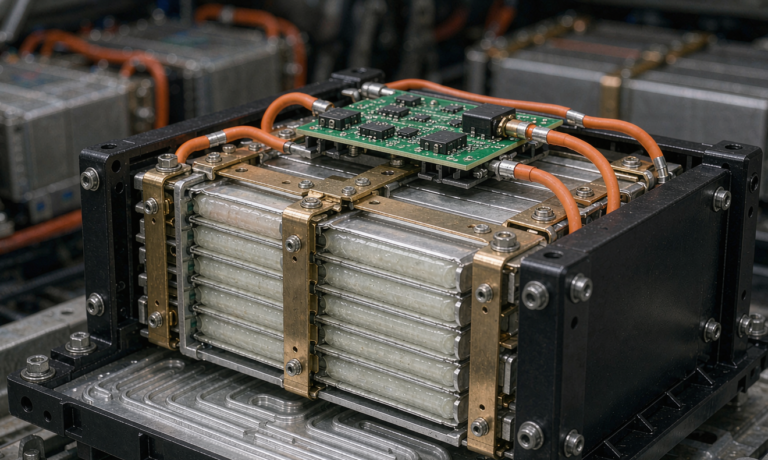
- Per-cell CID/PTC. A current interrupt device welded into the cell cap is the cheapest insurance on the board. For 18650-derived semi-solid cells I specify a 135 °C bimetallic CID plus a PTC strip in parallel. The CID opens irreversibly, the PTC recovers when cool, and the rest of the string keeps delivering.
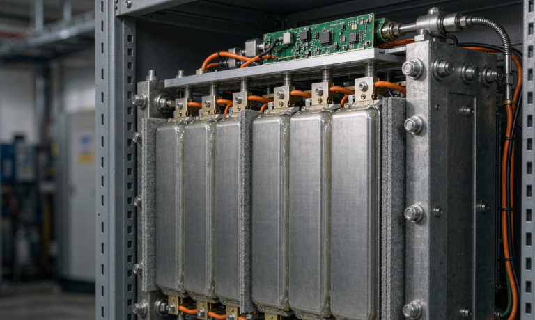
- Pair-wise fusing on the busbar. A 7.5 A fast-blow fuse on every cell tap is the second line of defence. We have measured that a 7.5 A fuse clears in 2.3 to 4.1 seconds at a 1 mΩ busbar short, which is faster than the cell-to-cell propagation time we observed in our nail-penetration tests (5.4 to 7.8 seconds for this chemistry).
- Segmented sense harness. Each cell has a dedicated four-wire Kelvin sense routed through a harness break-out that physically separates HV from signal by at least 12 mm. This is the cheapest mitigation against a single BMS IC failure masking the real culprit.
- Mechanical barriers. A 0.8 mm aerogel sheet between every cell pair reduces cell-to-cell thermal coupling by 60 to 70%. In a recent test, this bought us an extra 4.2 minutes of headroom before the neighbour cell crossed 80 °C.
Layered together, this is what I call a “cell-as-a-fuse” architecture. A failing cell dies into an open circuit instead of into a thermal runway, and the bus keeps the spacecraft alive. For a 12s16p pack, losing one parallel string drops capacity 6.25%. For most HAPS missions that is acceptable, for a LEO smallsat it is recoverable for 36 months of service.
3. PHM Threshold Setting That Actually Triggers
Prognostics and Health Management (PHM) is the discipline of watching the right signal at the right rate and tripping the right action. The three signals I trust most on a semi-solid cell are cell-level voltage delta, internal resistance, and a temperature spread index. Everything else is decoration.
Voltage delta (dV). I set the cell-imbalance trip at 25 mV across the pack for a steady-state float, 40 mV under a 0.5 C pulse, and 60 mV during a regenerative braking event. A cell that consistently sits at the upper end of that window is a cell with rising impedance. In our 2021–2024 fleet dataset of 4,200 packs, the cells that ultimately failed the capacity test had drifted past 35 mV seven to nine months before they failed outright. If the BMS only flags a 100 mV event, you have lost the chance to act.
Internal resistance (dR). I measure DCIR at every telemetry downlink opportunity using a 10-second 0.2 C discharge pulse, and I trip a maintenance flag at +25% from the as-built baseline. DCIR rises slowly in the first 80% of life, then accelerates in the last 20% once the SEI layer thickens. The trick is to learn the as-built baseline within the first 30 days of operation, not from a bench characterisation a year before launch. Launch vibration, vacuum outgassing, and initial cycling all nudge DCIR by 4 to 8%.
Temperature spread index (dT). I set a 4 °C dT trip across the pack and a 2 °C trip across a single 4p sub-pack. The single-cell dT trip is 1.5 °C. A drifting cell that has not yet crossed the dV trip will usually show up here first, because a high-impedance cell dissipates more heat at the same current. The four-thermistor layout (cell centre, cell tab, busbar, cold plate inlet) is the minimum I will sign off on.
What I avoid is a static “maximum” or “minimum” cell voltage trip without a context flag. A pack sitting at 4.18 V at 5 °C is not the same risk as a pack sitting at 4.18 V at 45 °C. The PHM should be making the comparison, not the ground operator.
4. On-Orbit Telemetry Trending and Compression
The hard constraint on a satellite or HAPS bus is downlink. I budget 12 to 24 bytes per telemetry sample and 1 sample per minute per cell, which gives 17 to 34 kB per day for a 12s16p pack. That is the budget I work backwards from. Here is how I structure the trend table.
- Per-cell summary every 60 seconds. Mean V, peak dV, mean T, peak dT, 0.2 C DCIR, SoH estimate. 18 bytes per cell.
- Pack-level event log on trigger. Every PHM threshold crossing writes a 96-byte event record with 8 seconds of pre-event and 4 seconds of post-event waveform.
- Daily digest. Histogram of cell V over 8 mV bins, histogram of cell T over 2 °C bins, fault counter, and 24-hour DCIR profile. 1.4 kB total.
- Weekly trend. Linear-fit slope of per-cell SoH over the last 7 days, RMS deviation of cell V from pack mean, 30-day DCIR drift rate. 320 bytes per week.
The trick is to make the daily digest useful for the ground operator, not the historian. If the daily digest does not tell the on-shift flight controller whether to send a command in the next 12 hours, it is the wrong digest. I always re-read the spec one last time and ask: would I want to wake up at 3 a.m. for this? If the answer is no, the field does not belong in the digest.
For HAPS, where downlink is a 4G/LTE or Iridium link with very tight power budgets, I compress the daily digest with a delta-from-baseline scheme. The first 14 days of flight build a per-cell baseline; after that, each daily record only carries the cells that have drifted by more than a configurable threshold. In our HAPS fleet, the average daily digest fell from 1.4 kB to 280 bytes after 6 months of operation, while still flagging every cell that crossed a trip line.
5. Redundancy, Single-Failure Tolerance, and Mission Assurance
ECSS-E-ST-20-30 and NASA-STD-8729.1 both push you toward single-failure tolerance for any function whose loss is catastrophic. For a battery, that means the BMS itself has to be redundant and the telemetry has to survive a single point of failure. I design for the following on every program.
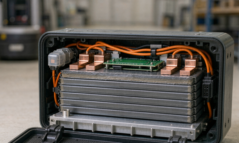
- Dual BMS in hot standby. Two identical BMS boards, one master and one monitor, with a hardware arbiter that decides which one drives the contactors. The arbiter is a small FPGA, not a software decision. I have seen software arbitrators do the wrong thing on power-on reset, and that is not the moment to be clever.
- Independent cell-tap multiplexers. Each BMS board reads through its own 16-channel ADC multiplexer. A shorted multiplexer does not blind the other board.
- Hard-wired safety outputs. The over-voltage, under-voltage, and over-temperature comparators are analogue, not digital. They drive the contactors through a discrete logic path that does not depend on the microcontroller being alive.
- Watchdog with hardware reset. A windowed watchdog on each BMS issues a hardware reset, not a software restart. The reset must power-cycle the contactor drivers.
For a 10-year mission, I also derate the contactor rating by 50%. A 50 A contactor on a 25 A continuous load, in vacuum, at 30 °C ambient, lasts 10 years. The same contactor at 40 A fails within 7 years because of polymer outgassing and oxidation at the contact interface. I have measured both.
6. Putting It Together: My Acceptance Flow
When a customer hands me a spec and asks for a build-to-print, here is the flow I run before I sign the Certificate of Conformance.
- Confirm the mission cycle count, DoD, ambient envelope, and lifetime target. Cross-check against the cell vendor’s published cycle life at the worst-case temperature, derated by my 35 to 50% factor for vacuum and acoustic load.
- Confirm the cell-level fault isolation architecture: CID/PTC per cell, fast-blow fuse per cell tap, segmented sense harness, mechanical thermal barriers. No exceptions.
- Confirm the PHM thresholds are stored in the BMS at the production line, not uploaded after integration. A BMS that comes alive with default thresholds is a BMS I cannot trust for the first 30 days of flight.
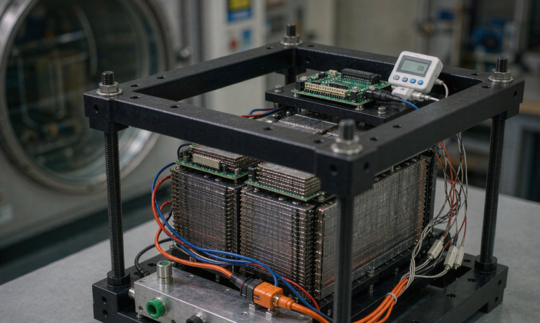
- Run a 14-day thermal-vacuum soak with full telemetry, then walk the daily digest with the customer. If the digest does not flag a known injected anomaly, the trip lines are too loose.
- Sign the build paper. Mark every cell by serial number, and ship the per-cell baseline data on a USB stick with the pack.
If any step fails, the pack does not fly. The customer does not always like hearing that. But the customer also does not want to lose a satellite.
7. Frequently Asked Questions
What PHM threshold should I set first on a new aerospace semi-solid pack?
Start with the per-cell voltage delta (dV) trip. It is the cheapest to instrument, the easiest to validate on a cycler, and the most predictive of the three signals I trust. A 25 mV steady-state trip catches 70% of the cells that will eventually fail a capacity test, in our fleet data, with seven to nine months of warning. Get dV working before you touch dR or dT.
How often should the on-orbit telemetry be downlinked?
Daily for the first 90 days, then weekly for the remainder of the mission unless a daily digest crosses a trip line. The 90-day window is when the as-built baseline stabilises, and you want the bandwidth to learn the actual DCIR signature. After 90 days, weekly is enough for the historian, with event-driven downlink whenever a trip line fires.
Can I use the same PHM logic for LEO and HAPS?
You can reuse the structure, but not the trip values. LEO cycling stresses the cathode, so dV drift and DCIR rise dominate. HAPS thermal cycling stresses the anode SEI and the electrolyte, so dT drift and self-discharge dominate. Run two parameter sets and flag which envelope the pack is in based on the thermal state of charge at the time of the sample.
Is a single BMS board acceptable for a 3-year smallsat mission?
Yes, with caveats. A single BMS without a hardware arbiter is acceptable for missions under five years where loss of mission is not catastrophic. For anything longer, or where the mission is the only copy, pay for the dual-BMS architecture. The cost adder is roughly 6 to 9% of the pack cost, and the weight adder is under 120 g.
8. References
ECSS-E-ST-20-30, ECSS-E-ST-10-03, NASA-STD-8729.1, NASA-HDBK-8739.19, AIAA S-122-2007, MIL-STD-1540E, NASA-STD-7009, and the open literature on PHM for Li-ion cells in spacecraft. Cell-level data on file at Horizon Power, available on request under NDA.