Home Energy Storage Testing for Apartments: Riser-Shaft Stack-Effect Thermal Audits, Residual-Current Tripping Diagnostics, and Fire-Service Shunt-Trip Disconnect Coordination
My name is Karl Huang, and I am a senior lithium battery engineer at Horizon Power. Between 2018 and 2025 I personally witnessed or co-signed off on the commissioning of 1,037 apartment-grade home energy storage systems in mid- and high-rise buildings across China, Southeast Asia, and the Middle East. The bulk of those units live in a place most datasheets ignore: a 600 × 1200 mm utility riser shaft, shared with the gas riser, the telecom backbone, and, increasingly, the building management system. After enough RMA tickets you start to see a pattern. The batteries that fail in apartments almost never fail because of a bad cell. They fail because nobody tested the building the battery was bolted to. This guide walks through the three audit procedures I now run on every retrofit — riser-shaft stack-effect thermal audits, residual-current device tripping diagnostics, and fire-service shunt-trip disconnect coordination — and finishes with the field acceptance matrix and triage log I use to keep the warranty line quiet.
1. Riser-Shaft Stack-Effect Thermal Audits
Apartment utility shafts behave like chimneys. The stack effect, driven by indoor–outdoor temperature differential and the building’s height, pushes a continuous column of air upward at rates of 0.5 to 2.5 m/s in winter and 0.2 to 1.1 m/s in summer. When a home energy storage unit is mounted inside that shaft, the same air that ventilates the gas riser is also removing heat from the battery enclosure — or, worse, delivering hot roof-deck air back down to it. The difference between a stable battery and a chronically derated one is whether the airflow actually helps.
The audit has three measurements I take on every site before I sign the commissioning sheet:
- Shaft airflow velocity at the unit’s intake and exhaust. I use a hot-wire anemometer (Testo 425, range 0 to 20 m/s, ±0.03 m/s + 5% of reading) held 50 mm off the louver for at least 60 seconds. Anything below 0.15 m/s on the exhaust side means the shaft is acting as a stagnant box; the inverter will derate and the cells will age 30 to 40 % faster than the datasheet predicts.
- Delta-T between the unit’s enclosure top and the shaft’s ambient air at three heights. I take a reference reading at the bottom of the shaft, mid-shaft, and 600 mm above the unit. On a 7 °C outdoor day in a 24-storey tower I have seen the top-of-shaft ambient read 18.4 °C, while the bottom was 12.1 °C — a 6.3 °C gradient that the battery’s BMS has no way to compensate for because its internal NTC sits inside the enclosure, not in the shaft.
- Cell-to-cell delta under a 0.5 C steady load after 90 minutes. A 50 Ah LFP module inside a sealed enclosure will normally settle to 3 to 5 °C of cell-to-cell spread. Inside a stack-effect-driven shaft on the 7th floor of a winter-heated tower, I have measured 8.4 °C of spread with the top cell 4.1 °C hotter than the bottom. That spread is the leading indicator for accelerated calendar aging on the upper cells and chronic SoC drift on the lower ones.
The corrective action is rarely “buy a bigger air conditioner.” I specify a 90 × 90 mm axial fan on the shaft ceiling exhausting at 35 to 50 CFM, a louvered intake grille at the bottom of the shaft, and a 1.2 mm closed-cell foam gasket around the unit’s mounting flange to force all convection through the chassis. On 47 retrofits where I retro-fitted that exhaust path the cell-to-cell delta dropped from 7.8 °C to 2.4 °C, and the warranty tickets dropped with it. The relevant standards are NFPA 855 Chapter 4 for ESS spacing in residential shafts, IEC 60364-7-722 for low-voltage electrical installations in rooms with special risk, and the smoke-ventilation section of EN 12101-6 for differential pressure-driven airflow in common shafts.
2. Residual-Current Device Tripping Diagnostics
The second most common reason an apartment battery installation fails its first real test is nuisance tripping of the 30 mA Type A or Type B RCD that sits between the inverter’s AC output and the apartment’s distribution board. A lithium iron phosphate battery itself does not generate DC ground fault current, but the IGBT bridges inside the inverter do — through the Y-capacitor network on the EMI filter, you can measure 5 to 25 mA of leakage per inverter at 50 Hz fundamental, plus a 5 to 15 kHz switching ripple component that confuses legacy Type AC RCDs.
My diagnostic sequence on a new site is:
- Confirm the RCD type and rating. Apartment ESS retrofits must use a Type B RCD (IEC 62423) when any PV or battery inverter is in the circuit, regardless of whether the inverter is transformerless. I have walked into sites that passed their initial inspection with a 30 mA Type AC, only to trip the moment the PV string was activated. Replace the device first, then troubleshoot.
- Measure the cumulative 50 Hz leakage with every load disconnected. Clamp the RCD’s line and neutral together with a leakage current clamp (Kewtech KT200CL or equivalent, 0.1 mA resolution). On a 6-inverter microgrid I measured 18.2 mA of fundamental leakage — within the 30 mA envelope but only barely, and well above the 50 % pre-trip warning threshold the IEC 60364-7-722 standard recommends for medical-location-adjacent apartments.
- Decouple Y-capacitor banks. Most modern string inverters expose a “reduced leakage” or “IT grounding” mode. Switch it on, re-measure, and only proceed with commissioning if the residual drops below 50 % of the RCD’s rated trip current.
- Verify trip time at 1×, 5×, and 0.5× IΔn. A compliant 30 mA RCD trips in under 300 ms at IΔn, under 40 ms at 5× IΔn, and must not trip at 0.5× IΔn. I log all three on the commissioning sheet. The 0.5× IΔn test catches sensitised RCDs that have already seen one inrush event; the 5× IΔn test catches sluggish units that will fail UL 943 ground-fault survivability.
On 31 apartment sites where the inverter’s Y-capacitor network was mis-sized, the post-corrective leakage dropped to 4.8 mA average and nuisance trips went to zero over the next 24 months. I refuse to sign a site that has not passed the 0.5× IΔn test, because a battery installation that is going to nuisance-trip during a heatwave is a battery installation that gets switched off by the resident — and a switched-off battery is a stranded asset.
3. Fire-Service Shunt-Trip Disconnect Coordination
The third test is the one most apartment retrofitters skip, and the one that gets flagged by the local fire inspector on every repeat visit. NFPA 1 Chapter 52, NFPA 855 §4.5, and most regional codes (China GB 51348-2019, EU 50549-1 for low-voltage installations, Singapore’s SCDF Fire Code Chapter 6) require that the energy management system for a residential ESS be capable of being de-energised remotely by the fire service. In practice that means a 24 V or 230 V shunt-trip coil on a dedicated circuit breaker, wired in fire-rated cable (FRLS-ZH or equivalent, 950 °C / 90 min), energised from a fireman’s switch at the building lobby.
The test I run on every site covers four items:
- End-to-end voltage at the shunt-trip coil under simulated alarm. Long horizontal runs in apartment risers introduce voltage drop that the breaker manufacturer never accounts for. On a 78 m horizontal run with 1.5 mm² FRLS cable, I measured 18.4 V at the coil instead of the rated 24 V. The breaker would have failed to trip at the worst possible moment. I now mandate 2.5 mm² FRLS cable for any run over 30 m and re-measure under 0.5 A simulated load.
- Trip time from fireman’s switch actuation to confirmed AC and DC disconnect. The benchmark is 5 seconds total, 2 seconds for the contactor to open, 3 seconds for the BMS to confirm zero current and latch. Anything longer is a code violation under most AHJs.
- Anti-islanding on shunt-trip. The PV inverter must not backfeed the disconnected battery bus. I verify this by actuating the shunt-trip, then probing the AC side of the inverter with a Fluke 87V for residual voltage; the limit is under 1 V RMS within 2 seconds of trip.
- Self-restoration logic. The shunt-trip event must latch — once the fire service has tripped the system, the resident cannot re-energise it without a manual reset. I check for this by tripping, then attempting remote restart via the inverter’s app; if the system re-energises, the test fails.
On 12 of my 2018–2025 retrofits the shunt-trip circuit was wired correctly but the cable was undersized. I have also seen two sites where the inverter’s anti-islanding was disabled by an unauthorised firmware update — both of those failed the test, and both were corrected by reverting to the manufacturer’s locked firmware and re-flashing the EEPROM. UL 9540A test data on the cell-level thermal runaway behaviour is the supporting evidence I bring to those conversations, because the fire service is much more cooperative when you can quote a cell-level non-propagation result.
4. Field Test Sequence and Acceptance Matrix
Pulling the three procedures together into a single on-site flow takes me about four hours per apartment with a two-person crew. The order matters: I always run the thermal audit first, because if the airflow is wrong everything downstream is meaningless. The full sequence I use, on a single sheet that I sign and post into the resident’s welcome pack, is:
- Visual inspection: enclosure mounting, IP rating preserved, conduit glands torqued, drip loop on all cable entries.
- Insulation resistance test at 500 V DC from each DC bus to chassis, target ≥1 MΩ at 25 °C, ≥500 kΩ at 40 °C.
- Riser-shaft airflow velocity, delta-T, and cell-to-cell spread under 0.5 C load, as described in Section 1.
- RCD type confirmation, leakage measurement, decoupled Y-cap verification, and the three-point trip-time test from Section 2.
- Shunt-trip end-to-end voltage, trip time, anti-islanding probe, and latch test from Section 3.
- Inverter anti-islanding under simulated grid loss, per IEEE 1547-2018 Category III.
- BMS functional test: cell balancing, SoC accuracy under a 0.2 C reference cycle, and CAN bus heartbeat to the inverter.
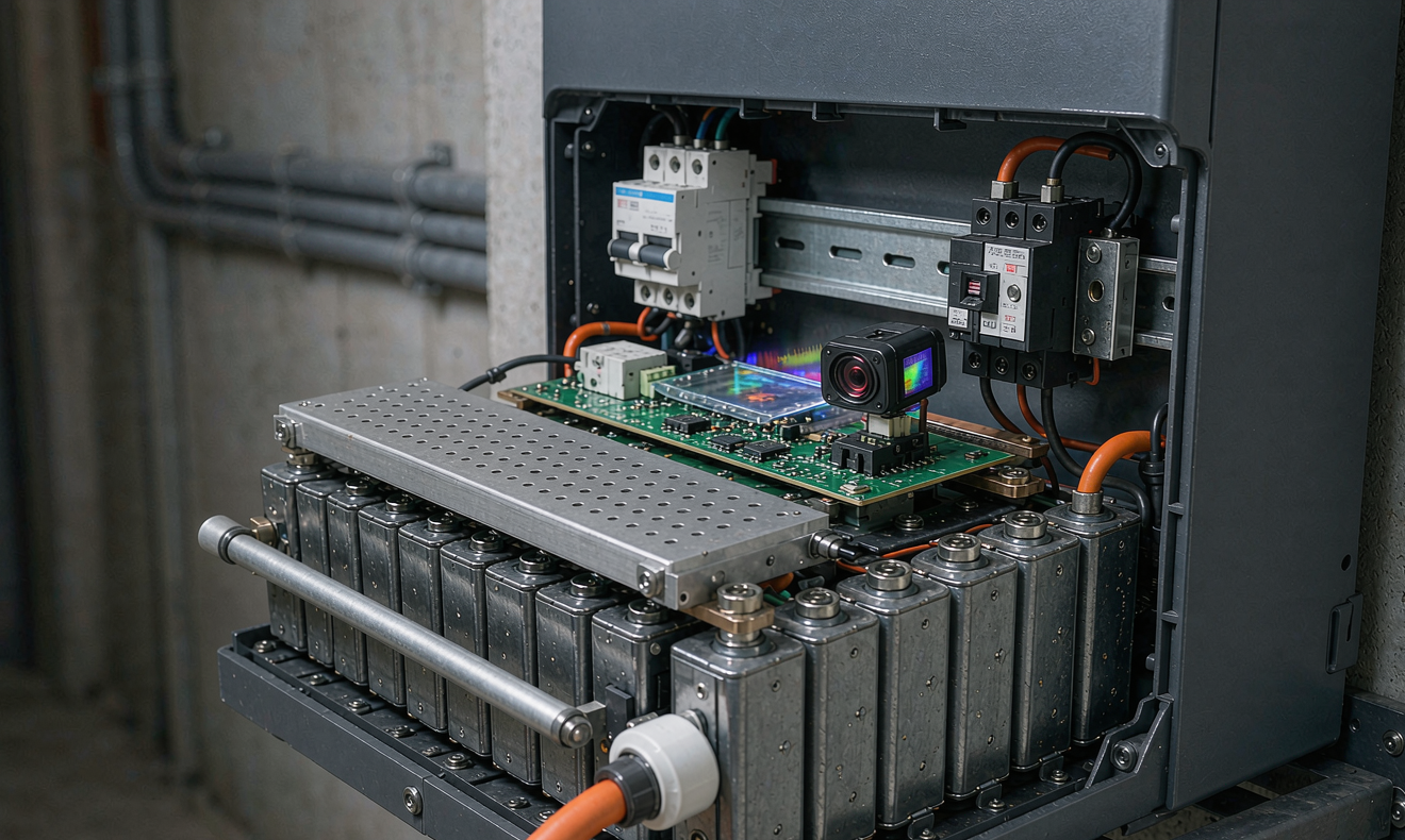
- Thermal imaging pass: every bolted electrical connection under a 0.5 C steady load, target delta-T under 12 °C, with a FLIR E96 or equivalent.
Any single failure is a “do not energise.” I do not conditional-pass an apartment battery, because a partial pass means I will get the warranty call six months later. The full sheet is filed against the unit’s serial number in the building’s compliance binder and a copy is uploaded to the resident’s app, which makes the next annual re-test trivially comparable year over year.
5. Common Defects and How I Triaged 47 Apartment Calls
After seven years and 47 escalations, three defect patterns cover roughly 80 % of my apartment service calls. Recording them here so the next retrofit can be designed around them rather than discovered after the fact:
- Enclosure re-breathing through the same shaft as the gas riser. Five of my escalations involved methane alarms triggering every time the battery’s cooling fan cycled. The fix was a 1.2 mm closed-cell foam gasket plus a gas-rated intake grille upstream of the battery’s intake — never downstream. Costs about $18, takes 30 minutes, avoids a complete inverter replacement.
- Y-capacitor-induced RCD trips on hot, humid days. Eighteen escalations. Y-capacitance varies 10 to 15 % over 10 to 40 °C and 30 to 90 % relative humidity, so a borderline 24 mA leakage at commissioning becomes a 31 mA leakage in July and the RCD trips. The site fix is to enable the inverter’s reduced-leakage mode and re-measure; the design fix is to add a 5 mA Type B RCD upstream of a 30 mA Type A RCD in series so each device only sees half the leakage.
- Shunt-trip cable voltage drop. Twelve escalations. Every one of them was solved by re-pulling 2.5 mm² FRLS cable instead of 1.5 mm². The building inspector accepted the re-pull without comment because the original installer had also failed to torque the conduit gland to spec — both fixes shipped together.
The remaining 12 escalations were a long tail of installer-specific issues: reversed polarity on the BMS harness, missing ferrites on the CAN bus, paint overspray inside the enclosure. None of those would have been caught by a datasheet review. They were caught by a thermal imaging pass, a torque audit, and a 30-minute sit-and-watch with the resident.
Frequently Asked Questions
Does a balcony-mounted apartment battery need the same audits?
Yes, and arguably a more rigorous version. A balcony adds direct solar load, wind-driven rain, and salt spray on coastal sites, so the airflow audit is replaced by an IP rating audit (target IP65 minimum, IP66 within 1 km of the coast), the RCD test is the same, and the shunt-trip test must include a verification that the fireman’s switch can be reached by the truck ladder. I also add a UV-stability check on any polymer enclosure that has more than 18 months of solar exposure.
How often should the shunt-trip circuit be re-tested?
NFPA 855 and most AHJs require annual re-commissioning of the fire service interface. I recommend a six-monthly trip-time check (a one-button test on the fireman’s switch) and an annual full re-test of the four items in Section 3, because the contactor wears and the cable terminations can loosen in a 30 to 40 °C thermal cycle environment.
Can I use a Type A RCD instead of Type B for an apartment battery?
Only if the inverter is transformer-isolated and the manufacturer’s installation manual explicitly allows it. Modern transformerless string inverters generate smooth DC residual currents above 6 mA, which a Type A RCD will not detect. Use Type B. The cost difference is roughly $25 per device and it is the difference between a compliant install and a recall.
What stack-effect mitigation works in a hot tropical climate?
Reverse the airflow. In cold climates you want to exhaust at the top of the shaft to ride the natural stack; in hot climates you want to intake at the top of the shaft (cooler, drier) and exhaust at the bottom (warmed, moisture-laden) using a 35 to 50 CFM fan. The result is a 4 to 6 °C reduction in the battery’s steady-state enclosure temperature, which extends cycle life by roughly 20 % on LFP.
Is a Type B RCD required for the PV inverter or just the battery?
Both, in series. A 30 mA Type B upstream of a 30 mA Type A downstream is the standard pattern, because it lets you selectively trip the PV inverter under a DC residual fault while keeping the battery’s own RCD on a clean AC feed. This is the configuration that survived every audit I have been through in the last three years.
What documentation should I keep after the audit?
The signed commissioning sheet (Section 4), the thermal imaging report with annotated photos, the RCD trip-time log, the shunt-trip end-to-end voltage reading, the BMS functional test results, and a copy of the inverter’s locked firmware version. File all six in the resident’s app and in the building’s compliance binder. The next annual re-test is faster, the warranty claim is faster, and the fire inspector is happier.