Semi-Solid State Battery Internal Pressure Sensing
Pressure is the one signal that tells you what is actually happening inside a sealed cell. Voltage and temperature are averages taken at the terminals and the case wall; pressure is a direct read on the chemistry and the mechanics working underneath them. On our semi-solid state battery programs, internal pressure sensing has moved from a lab curiosity to a routine qualification tool, and the reason is simple: a gel electrolyte gives you far less warning through voltage than a liquid system does. In this guide I will walk through where the pressure comes from, which sensors survive inside a cell, how we calibrate the measurement, and what the data is worth to a BMS designer.
Why Internal Pressure Is the Signal Worth Measuring
A lithium battery under normal operation hides its problems well. Capacity fade shows up over months, impedance growth over weeks, and by the time a voltage anomaly appears the cell has usually been degrading for a long time. Pressure behaves differently. Gas generation, electrode swelling, and electrolyte loss all push on the case from the inside, and they push early. In our formation data, cells that later failed a high-temperature calendar test already showed a measurably steeper pressure slope during their first 200 hours than the cells that passed.
The semi-solid case is special. In a liquid-electrolyte cell, a lot of early gas simply dissolves into the electrolyte reservoir and never reaches the headspace. A gel system carries only 10 to 20 weight percent liquid phase, held inside a polymer network, so generated gas has nowhere to hide. It collects in the pores and pushes directly on the stack. That makes pressure a more honest signal in a semi-solid state battery than in a conventional one, and it also means the pressure signature is different: sharper rises, less self-buffering, and a stronger correlation with interface quality at formation.
Where the Pressure Actually Comes From
Four sources matter, and they behave differently over life. First, gas from electrolyte decomposition: carbonate solvents break down at the anode surface into carbon dioxide, carbon monoxide, and ethylene, and any moisture above roughly 50 ppm reacts with the salt to release additional gas. Second, mechanical swelling: graphite expands about 6 to 8 percent during lithiation, and any silicon blending multiplies that, so a stacked electrode assembly grows in thickness every cycle. Third, thermal expansion: the liquid phase inside the gel expands far faster than the aluminum case, roughly an order of magnitude more per degree Celsius, so even a healthy cell breathes with temperature. Fourth, cure shrinkage and residual solvent vapor, which set the baseline during formation.
The tricky part is that these sources overlap. A prismatic cell that reads 80 kPa above ambient after formation might carry 30 kPa of gas, 35 kPa of thermally driven expansion, and 15 kPa of residual stack adjustment. Read the number without context and you learn almost nothing. Read its slope, its temperature correlation, and its hysteresis between charge and discharge, and you can separate the contributors. That decomposition work is most of what internal pressure sensing is really about.
Sensor Options and Where They Sit
We have qualified four families of sensors on pilot cells, each with a different compromise. The cheapest option is an external strain gauge bridge bonded to the case wall, calibrated to give kilopascals per millivolt. It adds no leak path and costs almost nothing, but it reads the case, not the cell interior, so case stiffness and mounting torque become part of your calibration.
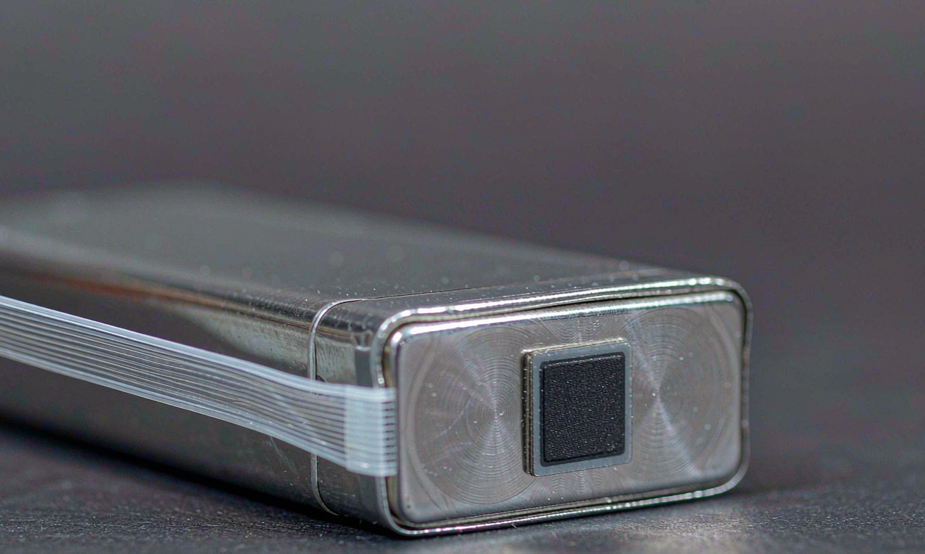
Thin-film piezoresistive sensors laminated directly into the stack give the cleanest mechanical reading. The constraints are severe: the sensor and its adhesive must tolerate the electrolyte, 85 degrees Celsius storage, and formation voltages without drifting or contaminating the interface. We gate every sensor lot with an isolation check of at least 100 megohms at 500 volts DC before it goes near a cell.
Fiber Bragg grating sensors are the best performer where budget allows. A hair-thin optical fiber embedded along the cell edge measures strain optically, is immune to electromagnetic interference, and can carry several gratings along one strand so pressure and temperature come off the same fiber. The interrogator unit is the expensive part, which is why fiber sensing lives in development cells and fleet canaries rather than every shipping unit.
Finally, there are non-intrusive estimates. Acoustic time-of-flight through the case and impedance-based inference both correlate with internal pressure, and both are attractive because they need nothing inside the cell. They are correlations, not measurements, and their accuracy degrades as the cell ages and its acoustic and electrochemical fingerprints drift. We use them for fleet-level screening, never for release decisions.
Sentinel cells instead of sensing everything
Because in-cell sensors add cost and a small risk of introducing a defect, we do not sense every production cell. The practical pattern is sentinel cells: sensor-equipped units built from the same lot, run through the same formation, and used to characterize the batch. Fleet telemetry from a few instrumented cells in the field then validates the model that the uninstrumented majority is judged against.
Calibration: Separating Swelling from Gas
Calibration is where most pressure-sensing projects fail, because the raw signal is contaminated by everything except the thing you care about. Aluminum expands about 23 micrometers per meter per kelvin, which on a typical case dimension translates to a pressure-equivalent error that dwarfs real gas evolution if you ignore it. So every sensor channel gets a paired temperature channel, and the firmware subtracts the thermal contribution before anything else is computed.
The second contamination is state of charge. Electrode swelling follows lithiation, so pressure rises with SOC and, worse, shows hysteresis: the pressure at 50 percent SOC on the way up is not the pressure at 50 percent SOC on the way down. We map that loop once per cell design at 10 percent SOC steps, store it as a reference curve, and judge cells by their deviation from the loop rather than by absolute values. A new cell is baselined during formation, and everything after that is delta analysis.
Our acceptance gate for the sensing chain itself is a zero drift below 2 kilopascals per 1000 hours at 60 degrees Celsius, verified on dummy cells loaded to the same stack pressure. If the sensor drifts more than that, the gas-generation trends you are trying to detect are inside the noise floor and the measurement is worthless.
Turning Pressure Data into Decisions
A pressure trace only earns its place in the product if something acts on it. In validation, the trace is most valuable during abuse testing: overcharge, thermal soak, and crush tests all produce a pressure excursion well before any voltage or temperature limit trips, and the time gap between the pressure inflection and the first hard fault is exactly the safety margin you are trying to quantify. We log pressure at 10 hertz alongside temperature and voltage for every abuse test, and the inflection time is a formal pass-fail input for pack-level review.
In the field, absolute pressure is nearly useless as an alarm because it varies with temperature and SOC. Rate of change is the signal. A healthy cell holds a stable, slowly declining pressure trend; a cell generating gas shows a sustained rise of tens of kilopascals per day that no thermal swing explains. The BMS logic we ship uses two thresholds: a soft warning band on sustained positive slope over 72 hours, and a hard trip when the rise rate itself accelerates, which is the classic precursor of a vent event. For stationary systems evaluated under UL 9540A style propagation testing, that early trip is what turns a cell-level event into a service ticket instead of an enclosure-level one.
Qualification Gates and Where the Standards Stand
Be clear about the regulatory picture: UN 38.3, IEC 62133-2, and IEC 62619 specify abuse tests and acceptance criteria, but none of them requires a cell to measure its own internal pressure. The sensor is a design and monitoring addition, which means nobody will audit your calibration, and also means the burden of proving the sensing chain is trustworthy sits entirely with the manufacturer. We treat it like any other safety-relevant component, with documented lot control, isolation testing, drift budgets, and a defined response when a sentinel cell reports out of family.
For any solid-state battery program moving toward automotive or stationary qualification, my recommendation is to instrument early and keep the sensing chain identical from development cells to pilot fleet. Changing sensor type between DV and PV destroys every baseline you built, and the whole value of pressure data is in the long trend lines.
FAQ
Does an internal pressure sensor shorten the cycle life of a semi-solid cell?
Not when it is integrated correctly. A laminated thin-film sensor occupies a fraction of a millimeter and sits outside the active electrochemical interface, so capacity impact is below our measurement resolution. The real risk is not thickness but contamination or a compromised seal, which is why every sensor lot passes electrolyte compatibility and isolation screening before it enters the stacking process.
Can pressure sensing replace temperature sensing in the BMS?
No, and you should distrust anyone who suggests it. Temperature drives the thermal expansion component of the pressure signal, so without a temperature channel you cannot separate real gas generation from a hot afternoon. The two signals only mean something together. Pressure adds an early-warning dimension that temperature lacks; it does not remove the need for the signals you already have.
What internal pressure does a semi-solid cell reach before the vent opens?
It depends on the case design, but in our prismatic builds the vent elements are tuned to open well above any operating pressure, typically in the range of several hundred kilopascals above ambient, while healthy cell life operates under 100 kilopascals. The design intent is that a cell should reach end of life and be flagged by its pressure trend long before the mechanical relief is ever involved.
How is fiber optic pressure sensing different from a strain gauge?
A strain gauge reads electrical resistance and needs wiring that survives the environment; a fiber Bragg grating reads an optical wavelength shift and brings nothing conductive into the cell. The fiber is immune to the electromagnetic noise around high-current testing, one strand can host multiple sensing points, and drift is far lower over long thermal cycling. The trade is cost: interrogators are expensive, so fiber stays on development and canary cells.
Is it practical to put a pressure sensor in every production cell?
Today, no, for cost and yield reasons. The practical architecture is sentinel cells: instrumented units from each production lot that characterize the batch, plus non-intrusive acoustic or impedance screening applied to the whole population. As thin-film sensor costs fall, per-cell sensing in high-value stationary and aviation packs is becoming realistic, and that is where we see it heading first.
How do you calibrate a sensor that is sealed inside a finished cell?
You calibrate the chain before it is sealed, not after. Sensors are characterized on dummy cells loaded to known stack pressures across the expected temperature range, the thermal and SOC contributions are mapped on instrumented formation cells, and shipped cells inherit that reference model. From then on you judge each cell against its own formation baseline, which is why preserving those baseline records is a formal requirement in our quality system.
Further Reading
References