Battery Solution for Airfield Approach Lighting
Approach lighting is the last guidance a pilot sees before the runway threshold, and it has to stay lit when the grid does not. I am Karl Huang, Senior lithium battery Engineer at Horizon Power, and over the past decade I have specified and commissioned backup power for airfield visual aids across tropical, alpine and coastal sites. A battery solution for airfield approach lighting is not a generic UPS bolted to a cabinet. It has to feed constant-current regulators, ride through transfer events, and survive salt, vibration and temperature swings that would crush a typical data-center pack. In this guide I walk through how I size, build and validate that backup power, and why lithium iron phosphate has become my default chemistry for the job.

Why Approach Lighting Needs Its Own Backup Power
An approach lighting system, often called an ALS, is the sequence of lead-in bars, crossbars and flashing lights that begins hundreds of meters before the threshold. In the United States the ALSF-2 and MALSR configurations are common, while in Europe and much of Asia the ICAO-aligned medium-intensity approach systems dominate. These lights are series-connected and fed by a constant-current regulator, almost always at a fixed 6.6 amperes on modern installations, with older airfields still running 20 or 30 ampere series circuits.
The safety case is simple. During a Category I, II or III approach the pilot is flying the lights, not the ground. If the primary utility feed drops and there is no standby source, the approach lights go dark and the approach is abandoned: a missed approach, a go-around, or a diversion that burns fuel and slots. That is why ICAO Annex 14 and the FAA advisory circulars treat standby power for visual aids as a certification item, not a nicety. The battery solution does not light the entire series circuit in every design, but it must keep the regulator energized, keep the control and monitoring electronics alive, and in many retrofit layouts it feeds an isolated section of the approach lead-in so the most critical bars stay visible.
Load Profile and Why You Size on the Regulator, Not the Lamps
Engineers new to airfield work make one mistake repeatedly: they size the battery on the wattage of the lamps. That is wrong. You size on the constant-current regulator cabinet standby load plus whatever isolated series segment the design intends to back up. A modern 6.6 ampere regulator draws a few hundred watts for its own power supply, cooling fans and controller, and the monitoring and communications module can add another 50 to 150 watts depending on whether it reports to the airfield lighting control system over fiber, Modbus or SNMP.
A single approach-lead-in branch you choose to isolate for backup might carry 1 to 4 kilowatts of effective load at the regulator output, because the series circuit holds current constant and the voltage scales with the number of series lamps and isolation transformers. In practice I budget 2 to 6 kilowatts for a typical approach-lighting backup package, held for a code-driven duration. The FAA and ICAO references push standby autonomy toward the period needed to complete an approach and a missed-approach sequence, commonly expressed as a minimum of about one hour of rated output at the regulated current, with design margins on top. I always add the regulator inrush and the fan start currents to the peak, because a regulator that drops out on transfer defeats the whole point.
Why I Specify Lithium Iron Phosphate for the Visual Aid Backup
For years the default was valve-regulated lead-acid, known as VRLA, in a vented cabinet. It met the letter of the standard and it was cheap to buy. It also failed the field: lead-acid hates partial state of charge, hates heat, and needs equalization and torch-and-ammeter attention most airfield maintenance teams do not have time for. I have pulled VRLA banks at 40 percent of nameplate capacity after three winters.
Lithium iron phosphate changed the math. A well-built pack holds 90 percent of capacity after 10 years of float-and-rare-discharge duty, runs from minus 20 to plus 60 degrees Celsius without a heater in most climates, and asks for nothing but a quarterly state-of-health ping. Energy density is not the driver here the way it is for a drone battery; reliability and maintenance avoidance are. A 48 volt or 51.2 volt rack of lithium iron phosphate cells delivers the 2 to 6 kilowatt load at a C-rate so gentle that calendar life, not cycle life, sets the replacement interval. I still specify a custom battery solution rather than an off-the-shelf cabinet, because the airfield environment demands corrosion sealing, a battery management system tuned for idle standby rather than deep cycling, and a transfer contactor that fails safe to the battery, not to darkness.
Enclosure, Corrosion and the Airfield Environment
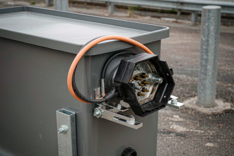
A battery solution for airfield approach lighting lives where the airplanes are. That means jet blast, de-icing fluid, coastal salt spray on island and coastal fields, and a temperature swing from a cold overnight to a heat-soaked equipment pad in hours. I seal the pack to IP65 as a floor, move to NEMA 4X with 316 stainless hardware on any coastal or de-icing-exposed site, and pressure-balance the enclosure with an ePTFE breathable vent so it does not pump moisture in and out with temperature.
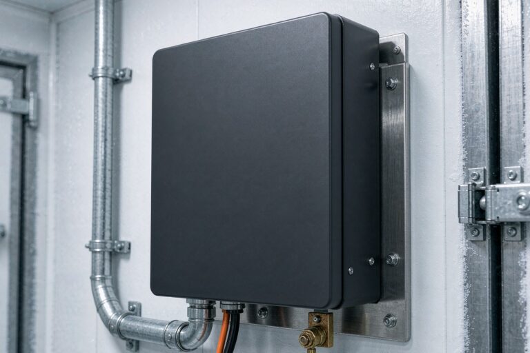
All busbars are tinned copper or nickel-plated, and I specify conformal coating to IPC-CC-830 on every control board. The rack mounts on isolation pads because the vibration spectrum near a threshold is not trivial, and a loose cell connection is a fire you do not get a second chance on. Thermal management is mostly about not cooking the pack. I keep the batteries out of direct sun, use a reflective enclosure skin, and if the site sees sustained pad temperatures above 45 degrees Celsius I add a small thermostatically controlled fan with its own backup. The regulator and battery share a cabinet on many retrofit designs, so I physically separate the cells from the regulator heat with an air baffle.
Standards, Transfer and Commissioning Tests I Run
The battery itself is built to UL 1973 and IEC 62619, with UN38.3 covered for transport and IEC 62133 referenced where portable sub-assemblies are involved. The airfield-side references matter more for acceptance: FAA L-821 for the power supply, L-824 for the series cable, and L-890 for the constant-current regulator, alongside ICAO Annex 14 Volume I for the visual aid availability targets.
Transfer time is the first thing I measure. When the utility drops, the load must move to the battery without a visible flicker on the approach lights, which means a static transfer switch or a contactor with a make-before-break sequence well under two seconds, ideally seamless. I then run a full rated-discharge test for the code duration, typically one hour at the regulated current, and log cell-to-cell voltage spread; anything above 30 millivolts at rest after the run gets the pack opened. Insulation resistance to the series circuit is checked with a 500 volt megger and must clear 100 megohms, and I finish with a self-test cycle where the battery management system forces a utility-loss event and confirms the approach branch stays lit and reports the alarm to the lighting control system.
Monitoring, Redundancy and What I Tell Owners to Expect
An approach-lighting backup pack is a standby asset you hope never to use, so monitoring is everything. I put a battery management system on every string with cell voltage and temperature at 1 hertz, pack current at 1 kilohertz, and a contactor trip under 5 milliseconds on a fault. The data rides out over Modbus or SNMP to the airfield lighting control and to our cloud dashboard, and a monthly self-test discharges a small fraction of capacity to confirm the string is alive without ever darkening a light.
For Category II and III fields I specify N plus one or two-N redundancy on the battery strings, because a single failed string during low visibility is the exact scenario the standard exists to prevent. Owners should expect essentially zero maintenance beyond the quarterly ping and an annual capacity verification; the pack should outlast the regulator it backs up. That is the whole point of moving from lead-acid to a lithium battery solution sized for idle standby rather than deep daily cycling.
Frequently Asked Questions
What size battery do I need for airfield approach lighting backup?
I size on the constant-current regulator standby load plus any isolated lead-in branch the design backs up, not on the lamp wattage. For a typical approach system that lands at 2 to 6 kilowatts held for about one hour, which a 48 volt or 51.2 volt lithium iron phosphate rack covers at a very gentle C-rate. Always add the regulator inrush and fan start currents to the peak before you finalize the amp-hour rating.
Can I keep using my existing lead-acid backup with a lithium retrofit?
You can reuse the cabinet and the series wiring, but I do not reuse the old VRLA cells. Lead-acid loses capacity in three winters of partial-state-of-charge standby and needs equalization most teams skip. A lithium iron phosphate retrofit drops in as a drop-in 48 volt or 51.2 volt block with its own battery management system, a fail-safe transfer contactor, and none of the watering or equalization. Keep the regulator; replace the chemistry.
How long must the approach lighting battery last during a power outage?
Long enough to complete an approach and a missed-approach sequence plus margin, which the FAA and ICAO references push toward a minimum of about one hour of rated output at the regulated current. I design for that hour at full load and then add a reserve, because the point is to keep the pilot flying the lights through a diversion, not to blink out at the worst moment.
Does the battery need to power the entire approach light system?
Not always. Many designs keep the regulator and the control electronics on battery and let the utility or a generator carry the full series circuit, while a retrofit layout may isolate the most critical lead-in bars on the battery so the approach stays visible even on total utility loss. The battery solution should match the availability target in ICAO Annex 14, not a one-size assumption about the whole field.
What standards apply to an airfield approach lighting battery solution?
The pack is built to UL 1973 and IEC 62619 with UN38.3 for transport, and IEC 62133 where portable sub-assemblies are involved. On the airfield side the references that matter for acceptance are FAA L-821 for the power supply, L-824 for the series cable, and L-890 for the constant-current regulator, alongside ICAO Annex 14 Volume I for visual aid availability.
How do I know the backup battery is still healthy years later?
A battery management system logs cell voltage and temperature every second and pushes it out over Modbus or SNMP, and a monthly self-test discharges a small fraction of capacity to prove the string is alive without darkening a light. An annual capacity verification against the original one-hour rating is the real proof; a lithium iron phosphate pack sized for idle standby should still clear 90 percent of nameplate after ten years.
Further Reading
References