Sodium-Ion Battery for EV Charging Station Buffer
Demand charges have quietly become the largest operating expense at many public charging sites, and I have watched this pattern repeat across every plaza we have engineered for. A four-stall DC fast charging site can draw more instantaneous power than a mid-size hotel, yet on a slow weekday it may sell only a few hundred kilowatt-hours of energy. A sodium-ion battery buffer closes that gap between what the grid connection allows and what the chargers demand. In this article I explain how we size such a buffer, why the chemistry suits charging duty, and which standards govern a safe installation.
Why DC Fast Charging Sites Need a Buffer
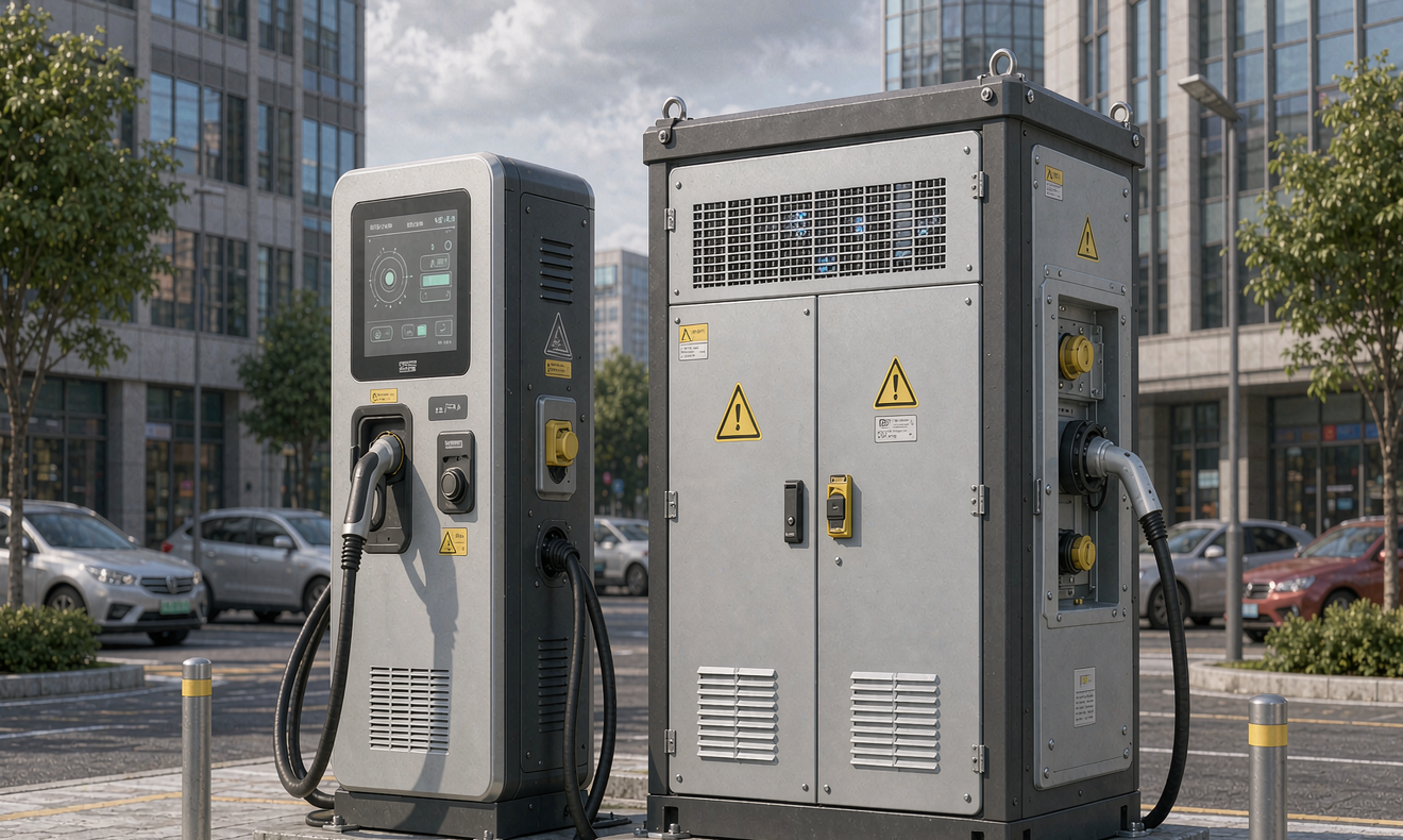
A modern DC fast charger is a brutally peaky load. A 150 kW unit pulls nameplate power within seconds of a session starting, and 350 kW units behave the same way. Four stalls running concurrently can hit 600 kW or more, which is roughly the peak demand of 30 to 60 homes arriving at once. The problem is that this peak may occur for only two or three hours a day while the site sits lightly loaded the rest of the time.
Utilities price that peak. Demand charges typically run 10 to 25 dollars per kilowatt per month in commercial tariffs. A single 600 kW monthly peak can therefore add 6,000 to 15,000 dollars to the bill before a single kilowatt-hour margin is counted. For sites still in permitting, the alternative is worse: upgrading the utility transformer and switchgear can cost 100,000 to 500,000 dollars with interconnection queues stretching 12 to 24 months.
A battery buffer attacks both problems. It shaves the site peak below the demand-charge threshold and it lets the station open years earlier on an existing service entrance. In our projects the buffer consistently repays its capital cost within three to five years purely through avoided demand charges and deferred grid upgrades.
Sizing a Sodium-Ion Battery Buffer
I size buffers from a four-step load study rather than a rule of thumb. Take a highway plaza with two 150 kW and two 350 kW stalls, a grid limit of 300 kW, and a coincident peak of 600 kW during the afternoon window.
- Step 1, power deficit: 600 kW peak minus the 300 kW service limit leaves a 300 kW gap the buffer must carry.
- Step 2, energy deficit: the busy window lasts three to four hours, so the gap consumes roughly 900 to 1,200 kWh of delivered energy per peak day.
- Step 3, conversion losses and usable window: round-trip efficiency of 90 percent and a usable state-of-charge window of 80 percent mean the installed capacity must be the deficit divided by 0.72.
- Step 4, degradation margin: I add 15 percent so the buffer still covers the peak at end of life, when only 80 percent of nameplate capacity remains.
For this site the arithmetic lands at roughly 1,500 to 1,700 kWh of installed sodium-ion capacity, delivered in three to four outdoor cabinets. Smaller urban sites with 150 kW stalls and a 200 kW service routinely need only 250 to 500 kWh. What matters is that the discharge rate stays modest: pulling 300 kW from a 500 kWh bank is a 0.6C load, comfortably within the continuous rating of a well-designed sodium-ion battery and gentle enough to protect cycle life.
Why Sodium-Ion Chemistry Fits Charging Duty
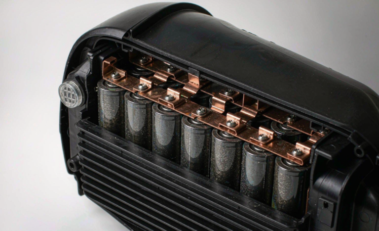
Stationary buffers care about cost, calendar life, and temperature tolerance far more than energy density, and this is exactly where sodium-ion chemistry outperforms the alternatives. A sodium-ion battery contains no lithium carbonate, no nickel, and no cobalt. Its hard carbon anode can be produced from biomass or asphalt-derived precursors, which stabilizes cell pricing on large multi-megawatt-hour orders in a way that lithium contracts no longer do.
Low-temperature behavior is the second decisive advantage. At minus 20 degrees Celsius a quality sodium-ion cell still delivers close to 90 percent of its room-temperature capacity, and it accepts charge at reduced current where a lithium iron phosphate cell blocks charging entirely below 0 degrees Celsius. For charging plazas in northern climates, that difference eliminates the heating budget that an LFP buffer would otherwise need.
Cycle life matches the duty cycle. Vendors now quote 3,000 to 6,000 cycles at 80 percent depth of discharge for prismatic sodium-ion cells, which translates to eight to sixteen years of one-peak-per-day buffering. Safety testing supports outdoor cabinet placement: nail penetration and overcharge tests on mature sodium-ion designs frequently end without fire, and thermal runaway, when forced, propagates more slowly and releases less heat than comparable NMC constructions. The lower gravimetric energy density of 100 to 160 Wh/kg is irrelevant here because the buffer sits on a concrete pad, not in a vehicle.
System Architecture: AC-Coupled or DC-Coupled
Architecturally, a charging buffer is either AC-coupled or DC-coupled, and the choice drives cost and efficiency. In an AC-coupled design the battery feeds a bidirectional inverter on the AC side of the service entrance. Modern string inverters reach 97.5 to 98.5 percent efficiency, and retrofitting one requires no modification to the chargers themselves. This is the configuration I recommend for existing plazas.
In a DC-coupled design the battery connects directly to the common DC bus inside the charging cabinets, ahead of the power modules. Energy flows through one conversion stage instead of three, saving four to six percent round trip, and the battery can share power electronics with the chargers. DC buses on current hardware sit between 800 and 1,000 volts. This architecture suits new-build sites where the charger vendor supports battery integration, and it trims cabinet count because no separate inverter block is needed.
Either way, the battery management system speaks CAN or Modbus TCP to the site controller. That controller coordinates state-of-charge limits with the charging network so the buffer never discharges below its reserve and always recharges during the tariff trough between 1 a.m. and 5 a.m.
Thermal Management and Outdoor Enclosure
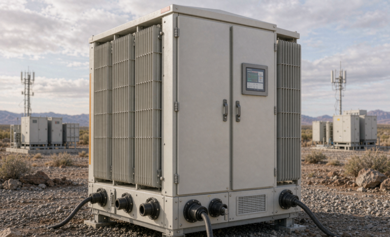
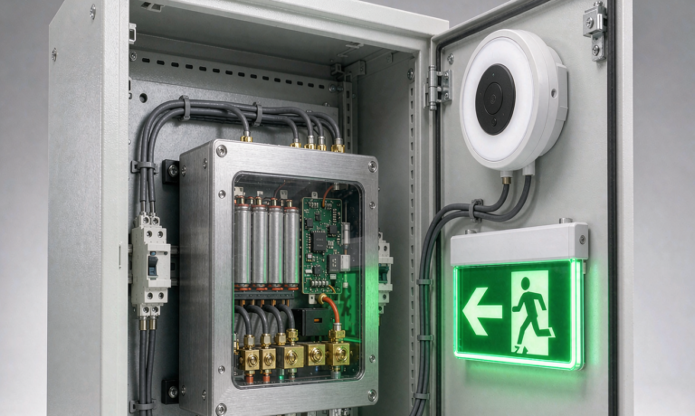
Charging plazas are outdoors by definition, so the buffer cabinet must survive them. I specify enclosures at IP54 minimum and IP55 where pressure washing or blowing dust is expected, which matches the practice used for the chargers themselves. Liquid-cooled or HVAC-conditioned cabinets hold the internal rack spread under 5 degrees Celsius, and the sodium-ion battery operates across minus 30 to plus 50 degrees Celsius with active heating below minus 10.
Condensation is the quiet killer. Every cabinet we ship carries a sealed enclosure with a pressure-relief vent sized per the UL 9540A test method, so deflagration venting is engineered rather than improvised. Cable entries enter from below through gland plates, and the pad is poured with a slight slope so meltwater never ponds against the door sill.
Standards and Compliance for a Charging Buffer
Compliance for a stationary buffer is well mapped even though sodium-ion is newer to the market. At cell level, every shipment must pass UN38.3 transport testing, and design validation follows IEC 62133-2 for portable-derived cells or the relevant sections of IEC 62619 at system level. IEC 62619 is the core safety standard for stationary industrial storage and is the one European utilities ask for first.
In North America the reference set is UL 1973 for the battery system, UL 9540 for the complete storage system, and UL 9540A as the thermal-runaway fire test that AHJs review during permitting. Installation sits under NEC Article 706, and if the buffer will ever export power, the interconnection must satisfy IEEE 1547. Coordination with the charging equipment itself follows IEC 61851 on the AC side. A vendor who cannot produce current UN38.3, IEC 62619, and UL 9540A reports for a sodium-ion product is not yet ready for a commercial charging deployment.
Frequently Asked Questions
How much energy storage does a DC fast charging site actually need?
Most four-stall plazas with a 300 kW service limit need 250 to 500 kWh of usable capacity, while highway sites with 350 kW stalls and heavy afternoon peaks land between 1 and 2 MWh. The correct number always comes from a load study of the power deficit between the service limit and coincident charger demand, never from a per-stall rule of thumb.
Can sodium-ion batteries deliver the power a charging buffer demands?
Yes. A typical buffer discharges at 0.5C to 1C, and prismatic sodium-ion cells are rated for 1C continuous and 3C pulse discharge. Because buffer power ratings are modest relative to installed capacity, the chemistry operates well inside its comfort zone.
How does a buffer reduce demand charges at a charging station?
The site controller watches the real-time grid draw and discharges the battery whenever total demand approaches the tariff threshold. Shaving a 600 kW peak down to 300 kW saves 3,000 to 7,500 dollars per month at typical commercial rates, which is what makes the buffer pay for itself in three to five years.
Do sodium-ion buffers work in cold climates where LFP struggles?
They do. A sodium-ion battery retains about 90 percent of capacity at minus 20 degrees Celsius and can accept limited charge below freezing, while an LFP system blocks charging below 0 degrees Celsius unless heated. Cold-climate sites therefore need a smaller heating budget and lose less range in winter.
What certifications should a charging station buffer carry?
Require UN38.3 for transport, IEC 62133-2 or IEC 62619 for cell and system safety, and in North America UL 1973, UL 9540, and a UL 9540A test report. The installation must comply with NEC Article 706 and, if export is planned, IEEE 1547.
Is DC-coupled or AC-coupled architecture better for a buffer?
AC-coupled systems are the pragmatic retrofit choice because they leave the chargers untouched and use proven 97.5 to 98.5 percent efficient inverters. DC-coupled designs save four to six percent in conversion losses and suit new-build sites whose charger vendor supports battery integration on a shared DC bus.
Further Reading
References