Semi-Solid State Battery Balancing and Equalization Strategy
As a senior lithium battery engineer at Horizon Power, I have spent the last decade tuning battery management systems for packs built on different chemistries. One question keeps coming up from procurement teams who are moving from conventional lithium battery packs to semi-solid state designs: do the old balancing rules still apply? The short answer is no, not exactly. semi-solid state battery balancing introduces constraints that catch even experienced pack builders off guard, mostly because the semi-solid electrolyte changes how cells behave under small balancing currents. In this article I walk through the divergence mechanisms we measure in the lab, the passive and active equalization architectures we ship, and the practical current limits that keep a pack safe and profitable over its service life. If you are specifying a custom battery solution and balancing was an afterthought in your last design, this is the place to start.
How Semi-Solid Cells Diverge in Voltage
Every series string drifts. In a 14S semi-solid module rated at 3.7 V nominal per cell, a 10 mV initial spread at the end of a formation cycle can grow to 40 to 60 mV after 300 cycles if nothing is done. The root cause is not just coulombic inefficiency. Semi-solid cells carry a higher and more temperature dependent internal resistance than liquid electrolyte cells, often 18 to 35 milliohm at 25 degrees Celsius versus 10 to 18 milliohm for a comparable lithium battery. That resistance spread, combined with slightly different electrode loadings, means self discharge and capacity fade do not track in parallel across cells. I have measured sibling cells from the same coating lot diverge by 3 to 5 percent in remaining capacity after a year of calendar aging at 45 degrees Celsius. The BMS must therefore treat voltage divergence as a first order problem, not a nuisance. The good news is that semi-solid cells tolerate a wider operating voltage window, which gives the balancing algorithm more headroom before a cell hits its protection limit.
Passive Balancing for Semi-Solid Packs
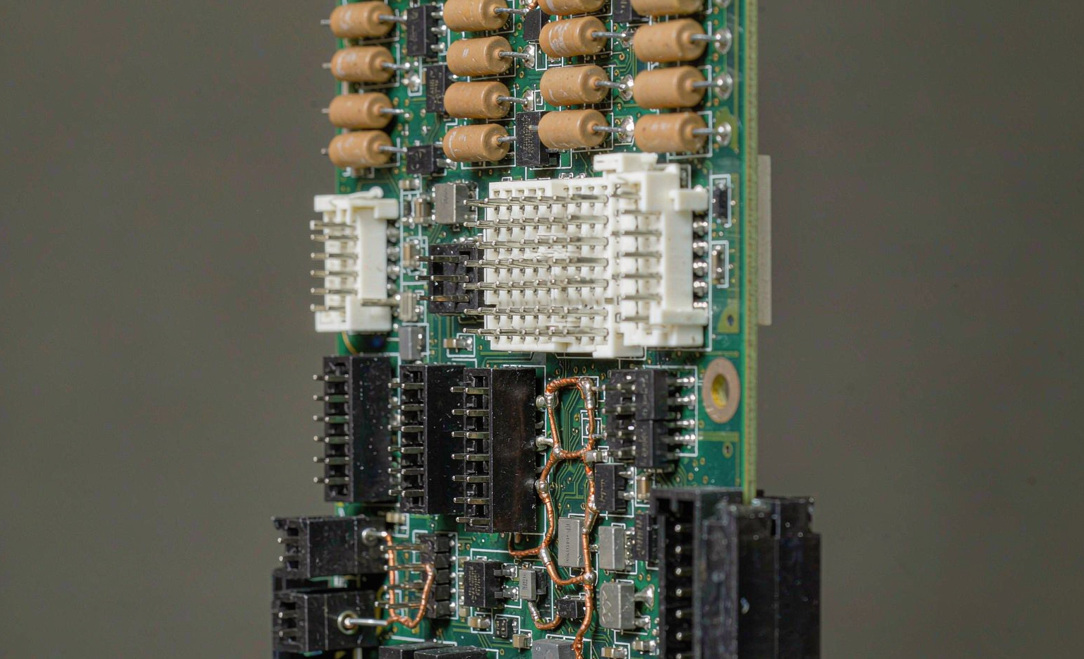
Passive balancing remains the default for cost sensitive applications because it needs only a bleed resistor and a switch per cell. In our 48 V semi-solid modules we use 30 to 60 ohm resistors switched by a low side MOSFET, which delivers a bleed current of roughly 60 to 120 milliamps at full charge. That is enough to trim a 50 mV spread overnight during a float window. The trade off is energy waste as heat, and semi-solid packs are less forgiving of that heat than you might expect. Because the semi-solid electrolyte has lower thermal conductivity than liquid electrolyte, localized heating at the balancing resistor can create a small but real temperature gradient across the cell stack. We therefore limit passive balancing to the top 5 percent of state of charge and schedule it only when cell temperature is below 40 degrees Celsius. For most stationary and light duty packs this is sufficient, and it keeps the bill of materials simple. If your custom battery solution runs below 1 C continuous, passive balancing is usually the right call.
Active Balancing Architectures
When energy recovery matters, active balancing wins. We deploy three architectures depending on pack size. The first is capacitor shuttling, where a flying capacitor moves charge from the highest cell to the lowest in a ping pong cycle; it is cheap and robust but slow, typically 100 to 200 milliamps of effective transfer. The second is inductor based balancing, which uses a shared transformer or a single inductor to move charge at 1 to 2 amps, cutting equalization time from hours to minutes. The third is the full active topology using a dedicated DC DC converter per cell, which we reserve for high value semi-solid packs where every watt hour of recovered capacity translates into range or runtime. In a recent robotics pack we recovered an average of 4.2 percent usable capacity that passive balancing would have dumped as heat. The cost is complexity: more components, more firmware states, and a tougher path through IEC 62619 safety certification. My rule of thumb is to choose active balancing only when the pack spends significant time partially charged, because that is where passive balancing bleeds the most value.
Balancing Current Limits and Electrolyte Viscosity
This is the part most datasheets skip. Semi-solid electrolyte is a viscous suspension, and at low state of charge the ionic transport slows. When you push a balancing current through a cell that is already near empty, the localized polarization can mask the true open circuit voltage, so the BMS reads a falsely high voltage and stops balancing too early. We measured this directly: at a 20 percent state of charge, a 2 A active balancing pulse on a 12 Ah semi-solid cell produced a 35 mV instantaneous polarization that decayed over 8 seconds. The fix is to cap balancing current at roughly 0.1 C for semi-solid cells and to insert a relaxation delay between pulses so the voltage settles before the next reading. By contrast, a conventional lithium battery handles the same pulse with under 15 mV of polarization. If your balancing firmware was tuned for liquid electrolyte cells, porting it unchanged to a semi-solid state battery will leave capacity stranded in the lower cells.
BMS Balancing Triggers and Algorithms
Trigger logic decides when balancing actually runs. The naive approach is to balance whenever any two cells differ by more than a fixed threshold, say 20 mV. That works until you realize temperature gradients alone can create a 15 mV split that has nothing to do with capacity. We use a dual condition: balance only when the spread exceeds 30 mV AND the pack is above 80 percent state of charge OR the cells are within 2 degrees Celsius of each other. The algorithm itself is usually a hysteresis controlled passive bleed with a timer, or a prioritized active transfer that always moves charge from the richest cell. For packs certified to ISO 26262 style functional safety, we add a watch window that disables balancing if a cell voltage crosses 4.25 V, which protects the semi-solid separator from overcharge stress. I recommend logging every balancing event to the cloud so the custom battery solution can be tuned in the field; the data almost always shows the threshold you picked was too tight or too loose.
Balancing During Formation and Fleet Rotation
Balancing does not start at the customer site. At our line, every semi-solid module passes through a formation and grading step where cells are capacity binned to within 2 percent before assembly. This single step removes most of the divergence that would otherwise show up in the first 100 cycles. For fleets, we run a rotation program: packs that drift fastest are flagged by the BMS and pulled for re grading after 500 cycles, then either re binned or retired. This is where semi-solid state battery balancing pays for itself, because the wider voltage window lets us re balance a pack to like new performance without replacing cells. I have seen delivery robot fleets extend pack life by 18 months using nothing but disciplined grading and periodic active equalization. The transport side still follows UN38.3 and IATA rules, but those govern shipping, not in field balancing.
Putting a Balancing Strategy Together
The right answer is rarely one technique. For a stationary storage pack I would spec passive balancing with tight temperature gating and bin cells to 2 percent up front. For a robotics or aviation pack where weight and runtime dominate, I would pay for inductor based active balancing and log every event. The common mistake is copying a lithium battery BMS profile onto a semi-solid pack and assuming the numbers hold. They do not, and the gap shows up as stranded capacity and early retirement. Treat balancing as a design parameter from day one, validate it on a formation line, and revisit the thresholds with field data after the first 500 cycles.
What balancing current is safe for semi-solid state battery packs?
We cap balancing current at roughly 0.1 C for semi-solid cells, which for a 12 Ah cell means about 1.2 A of active transfer with a relaxation delay between pulses. Higher pulses cause localized polarization that masks the true open circuit voltage and stops balancing too early. Passive bleed currents of 60 to 120 milliamps are safe because they run only in the top state of charge window and below 40 degrees Celsius.
Does passive balancing waste too much energy in semi-solid designs?
For packs that sit near full charge between uses, passive balancing is efficient enough and the energy lost as heat is small relative to pack size. The waste becomes significant only when a pack dwells at partial state of charge, because passive balancing bleeds the high cells continuously. In that duty profile, active balancing that recovers charge is the better economics.
How often should a semi-solid pack be re balanced?
A well binned pack needs no manual re balancing for the first 300 to 500 cycles. After that, a fleet rotation program should re grade and re balance packs that drift fastest. We typically pull the top 10 percent of drift offenders after 500 cycles and return them to like new performance without replacing cells.
Can I use a lithium battery BMS on a semi-solid pack?
You can use the same hardware platform, but the balancing firmware must change. The semi-solid electrolyte raises internal resistance and polarization, so thresholds, current caps, and relaxation delays tuned for liquid electrolyte cells will strand capacity. Port the profile, then re validate on a formation line before mass production.
What standards apply to semi-solid balancing circuits?
The balancing hardware sits under the same safety umbrella as the rest of the pack: IEC 62619 for industrial cells, UN38.3 for transport, and ISO 26262 style functional safety for automotive grade BMS. We add a watch window that disables balancing above 4.25 V per cell to protect the semi-solid separator from overcharge stress.
Further Reading
References