
Drone Battery Design for Inspection UAVs: Engineering a
As a senior lithium battery engineer at Horizon Power, I have spent the better part of a decade on the bench with packs that never see a desktop. The inspection UAV is one of the few airframes where the battery is not really built for the propellers — it is built for the payload. When a drone is surveying a wind-turbine blade or a corroding bridge truss, the rotors are just a way to hold a sensor still in the air. The real deliverable is data: a clean gimbal frame, a stable RTK fix, a thermal map with no dropped pixels. Get the power wrong and the airframe still flies — but the inspection fails quietly. That is why drone battery design for inspection UAVs starts from the sensor rail, not the flight envelope.
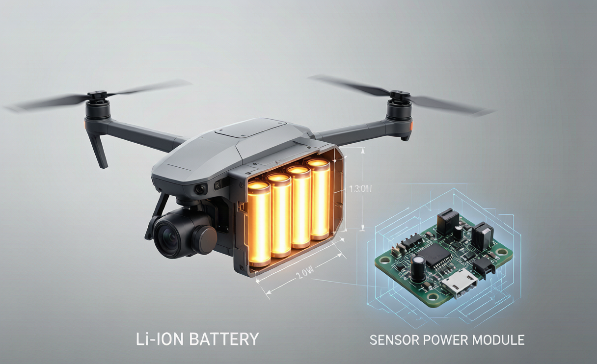
Why Inspection UAVs Design the Pack Around the Payload
Inspection duty is short-hop, station-keeping work. A typical asset survey means a climb to altitude, a long precision hover while the gimbal or LiDAR sweeps the structure, a gust-correction spike, then a short transit to the next asset. Propulsion power sits in a narrow band: about 1.5–2.2 kW hovering, with 10–25% overhead when a crosswind tries to shove the airframe off the structure. The battery has to feed two completely different loads off one chemistry — a brute-force motor bus and a fussy sensor bus — and the second one is what the customer actually paid for.
This is the first design fork. On a racing or delivery airframe the pack is judged by how much current it can dump and how many flights it survives. On an inspection airframe the pack is judged by whether the sensor kept producing usable data through every gust and voltage sag. I tell my team: for these builds, payload uptime beats raw endurance. A custom drone battery that gives you five clean minutes of survey is worth more than eight noisy ones.
Splitting the Bus: Propulsion Rail vs Isolated Sensor Rail
The single biggest decision in drone battery design for inspection UAVs is how you split the electrical architecture. The raw pack bus carries the nasty stuff: 100–160 A takeoff spikes, ESC switching noise, and the sharp voltage dip that happens the instant a gust hits. If you hang a gimbal IMU or an RTK module on that same unregulated rail, every motor transient shows up as micro-jitter in your footage or a dropped centimeter-level fix.
The topology I spec for inspection builds is a dual-stage bus. The propulsion rail runs more or less directly from the pack through a heavy interconnect — a 6S–12S platform where raising the cell count from 6S to 12S halves the current and quarters the I²R loss (a 60 A/6S run burns ~144 W in the harness; the same power at 12S is ~36 W). The sensor rail is a separate, isolated stage: the pack feeds an isolated DC-DC converter that produces clean regulated outputs (commonly 24 V for LiDAR, 12 V for the gimbal, 5 V for the companion computer), each with its own filtering and its own return path back to the airframe.
The Isolated DC-DC Stage That Holds the Sensor Through Sag
A pack can meet the headline spec and still corrupt a survey. We verify every pack at a DCIR below 10 mω measured at 1 kHz plus a 3C/10 s pulse, holding total sag under 8% of nominal. But during a hard gust the bus can still dip, and that is exactly when the converter earns its keep. The isolated stage carries 20–40 ms of holdup capacitance so the sensor rail barely twitches while the motor bus collapses and recovers. Common-mode filtering knocks down the switching noise the converter itself generates, and a tight voltage window (±2–5 mV balance, 20–30 mV cell-delta alarm) keeps the RTK from losing lock.
For the interconnect into that converter I still budget the harness resistance at under 15% of the pack DCIR — typically 1.5–1.8 mω using XT150/AS150 connectors with 8 AWG gold-over-nickel cable rated for 500–1000 mating cycles. Cheap tin-plated connectors grow micro-resistance after a few hundred cycles; on an inspection fleet flying daily that 0.25→2.5 mω creep becomes 25 W of heat in a 5 W housing. The isolated rail removes the symptom, but the harness removes the cause.
Avionics-Bay Integration: Keeping EMI Off the RTK and GPS
The DC-DC converter is a deliberate noise source, and the avionics bay is the most noise-sensitive real estate on the airframe. I treat the two as enemies that have to share a fuselage. The converter uses shielded inductors and spread-spectrum switching, and I keep it physically away from the RF front-end and the GPS/RTK antenna mast. The pack ground is co-located with the airframe ground plane so there is a single low-impedance return rather than a loop that radiates into the receiver.
Certification matters here too. Mounting and harness routing are validated against DO-160 and MIL-STD-810 random-vibration profiles across 5–2000 Hz, and we confirm the mounted resonance of the pack-and-bay assembly clears the rotor and blade-pass bands by more than 30%. A pack that hums at the blade-pass frequency will eventually fatigue a solder joint or shake a connector loose mid-survey. Integration is not a cosmetic step; it is what keeps the avionics honest.
Engine-Bay Mounting, CG and the Thermal Path
An inspection drone carries its pack low and centered so the center of gravity stays inside the flight controller’s window — roughly 25–35% of all-up weight, within ±15 mm across empty, nominal, and maximum-payload load cases. Get that wrong and the controller burns constant-thrust trim that no chemistry can recover, eating 8–12% of endurance for nothing. The pack is retained against landing loads yet releases in under 60 seconds for the 8–12 swaps a busy inspection day demands, with strain relief anchored within 30 mm to stop the fatigue failures mentioned above.
Thermally, a sealed composite fuselage gives you conduction, not convection. There is nowhere for heat to go, so I bolt the pack to an aluminum tray that is itself bolted to the skin, and I put the temperature sensor at the hottest predicted cell — not wherever the BMS happens to read easily. Discharge is gated to 15–45°C with a 40°C charge limit and a 5–15 W pad heater that pulls the core into the 10–25°C sweet spot on cold-dawn starts. For sealing I use IP5X–IP6X ingress protection plus conformal coating, potting, 316L stainless terminals, and a desiccant pack — no fan, because a fan is just a dust pump in a turbine yard.
A Worked Payload Power Budget
Numbers make the architecture real. A mid-size inspection quad with a stabilized gimbal, a thermal camera, and an RTK module draws roughly: gimbal 20–80 W, thermal camera 20–45 W, LiDAR (if fitted) 15–40 W, companion computer 10–25 W, RTK 5–12 W, and mission lights 5–20 W. The sensor suite alone is 70–200 W on top of the 1.5–2.2 kW propulsion floor.
Take a 12S 22 Ah NMC pack at 250 Wh/kg. Hover at 1.8 kW plus a 120 W payload is about 1.92 kW. With a 25–30% reserve for FAA Part 107 / EASA SORA margins you get roughly 0.55 kWh usable out of ~0.97 kWh installed — about 28 minutes of loiter, which is enough for a 10–14 asset tour before the regulated rail ever sees a low-voltage event. The point of the budget is not the minutes; it is proving the isolated sensor rail stays inside its window for the whole sortie.
Chemistry and Cell Choice for Inspection Duty
For an energy-limited, hover-heavy inspection profile I default to NMC/NCA cells at 200–250 Wh/kg with 500–1000 cycles — the best mass-to-energy trade for an airframe that is already payload-starved. On gusty coastal or mountainous sites I will spec high-power LiPo at 150–200 Wh/kg and 3–6 mω internal resistance for the burst headroom, accepting the shorter 150–300 cycle life. LFP at 120–160 Wh/kg and 2000–4000 cycles is what I put in the ground charging cart or a buffer pack, not the airframe. Semi-solid cells at 250–300 Wh/kg are qualifying now for inspection ships that need the extra loiter.
Cold is the silent killer of inspection schedules. Capacity fades from 100% at 25°C to about 85% at 0°C, 70% at −10°C, and 55–60% at −20°C. A 5–15 W pad heater restoring the core to 10–25°C recovers roughly a third of that loss — far cheaper than oversizing the pack by 30–45% to survive one cold dawn. That thermal design decision is part of the battery, not an afterthought bolted to the airframe.
From Spec to a custom battery solution
When a fleet operator comes to us, the design conversation starts with four numbers: the heaviest asset they inspect, the longest loiter leg they fly, the gust cadence at the site, and the avionics envelope they have to power. Those four inputs drive cell count, capacity, the isolation architecture, and the thermal path. That is how a generic request becomes a custom battery solution rather than an off-the-shelf brick that corrupts every survey.
Every build ships compliant: UN38.3 T.1–T.8, IEC 62133-2:2017, IATA 30% state-of-charge for transport, and the FAA/EASA 100–160 Wh per-pack ceiling with margin. We retire packs at 80% state-of-health, 2× baseline internal resistance, a 50 mV cell delta, or 5% puffing — whichever comes first. For a custom drone battery that is the difference between a fleet that quietly loses data and one that every survey trusts.
FAQ
Why not just use the same pack as a delivery drone?
Delivery packs are optimized for pulse current and fast swap throughput; they are not designed around a noise-sensitive sensor rail. Put a delivery pack on an inspection airframe and the gimbal and RTK will see every motor transient. The isolated, regulated sensor stage is what inspection work actually requires.
What does the isolated sensor rail actually protect against?
Voltage sag during gusts, ESC switching noise, and ground-loop radiation. The isolation plus 20–40 ms holdup means a momentary bus dip never drops the RTK fix or freezes the gimbal, so the survey data stays clean even when the airframe is fighting the wind.
How much endurance do I lose to the payload?
On a typical inspection quad the sensor suite draws 70–200 W on top of a 1.5–2.2 kW hover. With a 25–30% regulatory reserve you still get roughly 25–30 minutes of loiter on a 12S 22 Ah NMC pack — enough for a 10–14 asset tour with the sensor rail inside its window the whole time.
Which chemistry is best for inspection UAVs?
NMC/NCA at 200–250 Wh/kg is the default for mass-limited airframes; high-power LiPo suits gusty sites; LFP belongs in the ground cart; semi-solid is qualifying for long-loiter ships. Cold-climate fleets should pair any of these with a 5–15 W pad heater rather than oversizing the pack.
How do you keep the battery compliant for transport?
Every pack meets UN38.3 T.1–T.8 and IEC 62133-2:2017, ships at IATA-mandated 30% state-of-charge, and stays within the FAA/EASA 100–160 Wh per-pack limit. That lets operators carry spares on commercial flights and move fleets between sites without special permits.
The inspection UAV is the clearest proof that a drone battery is not a commodity. The propellers just keep the sensor in the air; the pack keeps the sensor honest. Design the isolated rail first, integrate the avionics bay with intent, and the data takes care of itself — which is the only thing the customer ever opens the report to see.





