Semi-Solid State Battery Calendering and Porosity Control
At Horizon Power, I spend a lot of time on the electrode production floor. Calendering is one of the steps that separates a good semi-solid state battery from a marginal one. It compresses the coated electrode web to a target thickness and density. In a semi-solid state battery, that step is critical because the electrolyte is only partially solidified and the electrode must leave enough open pore network for wetting while still hitting the energy density target. Get the porosity wrong and you will see high impedance, uneven cycle life, and in the worst case delamination between the active layer and the current collector.
What Calendering Changes in a Semi-Solid State Battery
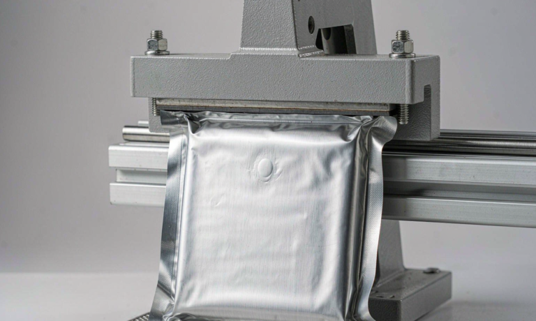
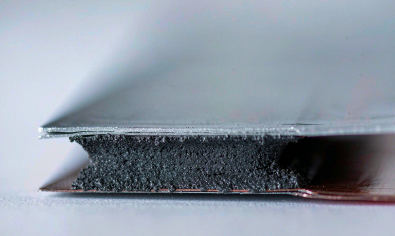
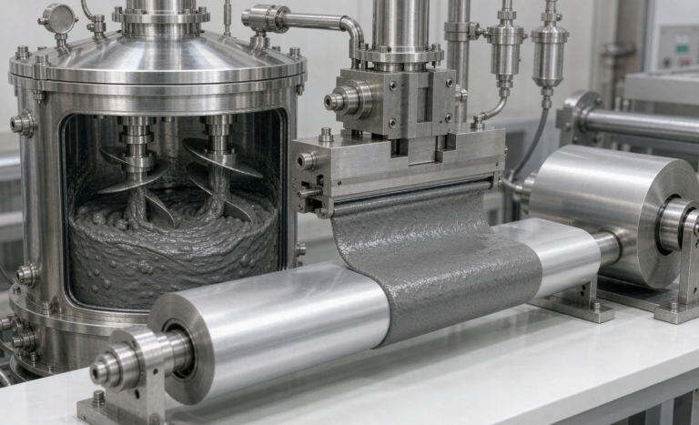
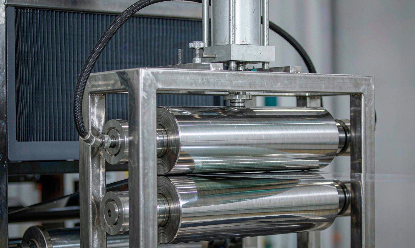
Calendering takes a loose, coated electrode web and turns it into a dense, mechanically stable sheet. The web passes between two heated rollers that apply pressure over a controlled gap. After drying, the electrode has a porosity of forty to fifty percent by volume. The calendering stand reduces that to the designed value, often twenty-five to thirty-five percent for a semi-solid state battery, depending on the active material, binder, and separator interface.
The goal is not to squeeze the electrode as hard as possible. Over-calendering crushes the particles, increases tortuosity, and closes the pore throats that the semi-solid electrolyte needs to penetrate. Under-calendering leaves the layer too soft for the winding or stacking steps that follow. A semi-solid electrolyte is more viscous than a liquid electrolyte, so it cannot easily fill very fine pores. That is why the porosity sweet spot for a semi-solid state battery is usually a couple of points higher than what we would accept in a conventional liquid-electrolyte lithium-ion cell.
I have also found that the pressure profile across the roll width matters more than people expect. A slight crown mismatch between the top and bottom rolls can create a density gradient from the center of the web to the edges. That gradient shows up later as uneven current distribution across the jelly roll or stack, which is exactly what we do not want in a high-voltage semi-solid pack.
Why Porosity Targets Are Tighter for Semi-Solid Cells
In a standard lithium-ion cell, liquid electrolyte wicks into the electrode pores through capillary action. In a semi-solid state battery, the electrolyte is a composite mixture that contains both a solid electrolyte phase and a small amount of liquid additive. The viscosity is higher and the wetting kinetics are slower. If the pore network is too closed, the electrolyte cannot reach the particle surfaces in the center of the electrode, and the cell develops localized high resistance.
We therefore set a dual target in the quality plan: bulk porosity and pore-size distribution. Bulk porosity tells us the average void fraction across the electrode. Pore-size distribution tells us whether the voids are connected and large enough for the semi-solid electrolyte to flow through. For a graphite anode in a semi-solid state battery we usually target twenty-eight to thirty-two percent bulk porosity, with no more than ten percent of pore volume below one micron. For a nickel-rich cathode, the target is thirty to thirty-four percent because the cathode particles are less conductive and need a slightly more open structure.
The tighter targets mean that small changes in roll force or roll temperature create measurable changes in cell impedance. We validate every new recipe with a three-cell pilot lot before we let it run on the main line. The pilot cells are cycled fifty times at room temperature and then checked for capacity fade and impedance growth. If the median impedance after cycling rises more than five percent, we open the calendering gap by ten to twenty microns and retest.
How Roll Pressure, Gap, and Line Speed Interact
On a production calendering stand, there are three knobs that matter most: roll pressure, roll gap, and line speed. Roll pressure is usually measured in Newtons per millimeter of web width and can range from one hundred to five hundred N per mm for semi-solid electrodes. Roll gap is the distance set between the rollers when the web is not present, and it is the dominant control for final thickness. Line speed determines how long the electrode sits under pressure and how much heat is transferred from the rolls to the web.
Here is the practical part. If you increase line speed without changing the gap, the electrode sees the same total pressure but for a shorter time. That usually means less densification and a slightly higher porosity. If you lower the roll temperature, the binder becomes stiffer, so the same gap setting gives a thicker web and lower density. If you increase pressure without tightening the gap, the web may walk sideways or develop wrinkles. These interactions are why we record all three variables together on the traveler and never change more than one at a time during a process change.
We also keep a close eye on roll wear. Even a few microns of wear in the center of the roll can create a thickness band that repeats every revolution. We measure roll runout weekly with a dial indicator and regrind when the peak-to-valley exceeds twenty microns. In a semi-solid state battery line, that maintenance discipline pays for itself quickly because the cost of a rejected batch is high.
Calendering Effects on Electrolyte Wetting and Interface Resistance
The whole point of calendering is to build an electrode that the semi-solid electrolyte can wet uniformly. After calendering, we cut small samples and run electrolyte uptake tests. We place a weighed drop of the semi-solid electrolyte precursor on the electrode surface and measure the spreading radius over time. If the electrolyte spreads to at least five millimeters in the first sixty seconds, we usually pass the sample. If it beads up, we know the surface energy or pore structure is wrong.
Interface resistance between the electrode and the separator is also affected by calendering. A too-smooth, glassy surface may look good under a microscope but can trap air pockets against the separator. A slightly textured surface, with controlled micro-roughness, gives the semi-solid electrolyte a path to spread laterally. We often run a light surface treatment, such as a controlled rewinding tension, after calendering to preserve that texture without adding loose particles.
Another subtle effect is how calendering changes the through-plane conductivity of the electrode. A denser electrode has more particle-to-particle contact, which helps electronic conductivity, but it also has a longer ionic path if the pores are too small. For a semi-solid state battery, ionic conductivity through the semi-solid electrolyte is the bottleneck. That is why we are willing to trade a small amount of electronic contact gain for a larger improvement in ionic transport.
In-Line Metrology and Quality Gates We Use on the Web
We do not wait until the end of the roll to check the electrode. The line has a beta gauge mounted right after the calendering stand to measure basis weight continuously across the web. Basis weight divided by the known coating solids loading gives us a running estimate of coating thickness. We cross-check that against a laser micrometer that measures total web thickness. If the two readings diverge by more than three percent, the line stops for a gap check.
Beyond thickness, we cut tail samples every five hundred meters and run a quick porosity measurement. The lab method uses an inert gas pycnometer on a small punched disc. It takes about ten minutes, so it is not truly in-line, but the interval is short enough to catch a drift before an entire shift is affected. We also measure peel strength between the coating and the foil. A calendered electrode should not lose more than five percent of its coating mass during a standard peel test. If it does, the binder has been over-worked or the foil surface preparation is wrong.
We are also evaluating an X-ray fluorescence gauge that maps active-material distribution across the web. It gives us a second channel for catching coating streaks that could be flattened by the rolls and missed later. In a semi-solid state battery, a coating streak becomes a local impedance hot spot, so we stop the line and fix the coater rather than let it run.
A Worked Example: Setting a New Cathode Recipe on the Calendering Stand
Last quarter we brought a new high-nickel cathode into our semi-solid state battery pilot line. The first setting we tried was a two-hundred-micron roll gap, eighty degrees Celsius roll temperature, and twenty meters per minute line speed. The resulting thickness was one hundred and ninety microns, which was within the drawing tolerance, but the porosity was twenty-four percent. That was too low for the semi-solid electrolyte we planned to use.
We opened the gap to two hundred and ten microns and raised the roll temperature to ninety degrees Celsius to let the binder relax more. The next roll gave us a porosity of thirty-one percent and a thickness of one hundred and ninety-five microns. The electrolyte uptake test showed full wetting in forty seconds. We then built six single-layer pouch cells and cycled them for one hundred cycles at one C. Capacity retention was ninety-seven percent and impedance growth was under three percent. That became the released setting for the recipe.
The lesson from that exercise is that you cannot copy settings from one electrode chemistry to another. Even within the same family of semi-solid state battery materials, the particle morphology and binder content change the response to pressure. We now require a design-of-experiments screening for every new active material before it is released to volume production.
Frequently Asked Questions
What is the typical porosity range for a semi-solid state battery electrode?
For most graphite anodes and nickel-rich cathodes we run, the target is between twenty-five and thirty-five percent bulk porosity. The exact number depends on the electrolyte viscosity and the particle size distribution.
How does calendering pressure affect electrolyte wetting?
Higher pressure reduces porosity and can close small pores. If the pore throats become too narrow, the semi-solid electrolyte cannot penetrate easily, which causes high interface resistance and uneven capacity.
Why is density variation across the web a bigger risk in semi-solid cells?
A semi-solid electrolyte does not redistribute as easily as a liquid electrolyte. A locally dense spot stays dry, creating a high-resistance region that limits power and can accelerate aging.
What in-line gauges are used to monitor electrode density and thickness?
We use a beta gauge for basis weight, a laser micrometer for total thickness, and periodic lab checks with gas pycnometry for true porosity. X-ray fluorescence gauges are also useful for mapping active material distribution.
Does calendering improve or reduce the energy density of the electrode?
It improves volumetric energy density by packing more active material into the same thickness, but only up to a point. Over-calendering hurts ionic transport and can lower usable energy density in a semi-solid state battery.
How do you set the roll gap when switching between cathode and anode recipes?
We run a short design-of-experiments matrix that varies gap, pressure, and temperature, then select the setting that gives the target porosity, good peel strength, and full electrolyte wetting before releasing the recipe to volume production.
Further Reading
References