Semi-Solid State Battery Integration for EV Packs
Over the last three years I have watched the conversation around the semi-solid state battery shift from chemistry to packaging. The cells themselves are impressive, but the moment you try to bolt them into a 400 V or 800 V electric vehicle pack, a different engineering discipline takes over. Integration, not electrochemistry, is where programs win or lose. As a senior lithium battery engineer who has taken several pack designs from prototype to production line, I want to walk you through what integration actually demands when the cells sitting on your bench are semi-solid rather than the liquid-electrolyte lithium battery you grew up with.
The short version: semi-solid chemistry gives you roughly 300-360 Wh/kg at cell level, about 10-20% above the best NMC and far above LFP’s 160-200 Wh/kg. That headroom is real, but only if your structural, electrical, and thermal integration can absorb the new behavior without eating the gains back through oversized enclosures, heavy busbars, or conservative cooling margins. Below is the playbook I use.
Why Integration Is the Real Bottleneck, Not the Chemistry
When customers ask me whether a semi-solid state battery is “better,” I reframe the question. A higher energy density cell that forces you to add 12% pack mass in structural adhesive and 8% in copper is not a net win. The integration step is where cell-level advantages get translated, or lost, at pack level. In my experience the three levers that decide the outcome are structural bonding, electrical joint resistance, and thermal coupling. Get those right and you keep 85-90% of the cell-level advantage at the system level. Get them wrong and the gap to a well-integrated NMC pack narrows to single digits.
This is also where a custom battery solution earns its keep. Off-the-shelf pack architectures designed around liquid-electrolyte cells rarely fit semi-solid behavior, especially on cell swelling and compression. We almost always re-derive the mechanical stack from the cell outward rather than reusing a legacy enclosure.
Cell-to-Pack Architecture and Structural Bonding
The first decision is whether to keep modules at all. For semi-solid cells I now favor cell-to-pack (CTP) for most EV programs because the energy density headroom justifies dropping the module housing. The trade-off is that every cell becomes a structural member, so the bonding strategy carries the crash and vibration load directly.
We bond cells to the cooling plate and to each other with a structural adhesive rated above 5 MPa shear strength, then apply a controlled compression force in the 0.3-0.6 MPa range. That compression is not cosmetic. Semi-solid cells swell slightly under cycle life, and if you under-compress, the swell accumulates as internal stress that raises DCIR; if you over-compress, you crush the separator. I specify an end-of-line compression check with Cpk ≥ 1.67 because this single parameter predicts pack longevity better than any marketing number on the cell datasheet.
Mechanically, the pack must survive UN38.3 T.5 vibration (7-200 Hz random, 0.8 grms per axis over three axes, 3 hours each) and T.6 mechanical shock (150 g, 6 ms half-sine) before it ever reaches a vehicle validation track. Those are the same bars a conventional lithium battery pack must clear, so the integration work is where semi-solid earns the right to ship.
Electrical Integration: Busbars, Welds, and Resistance Control
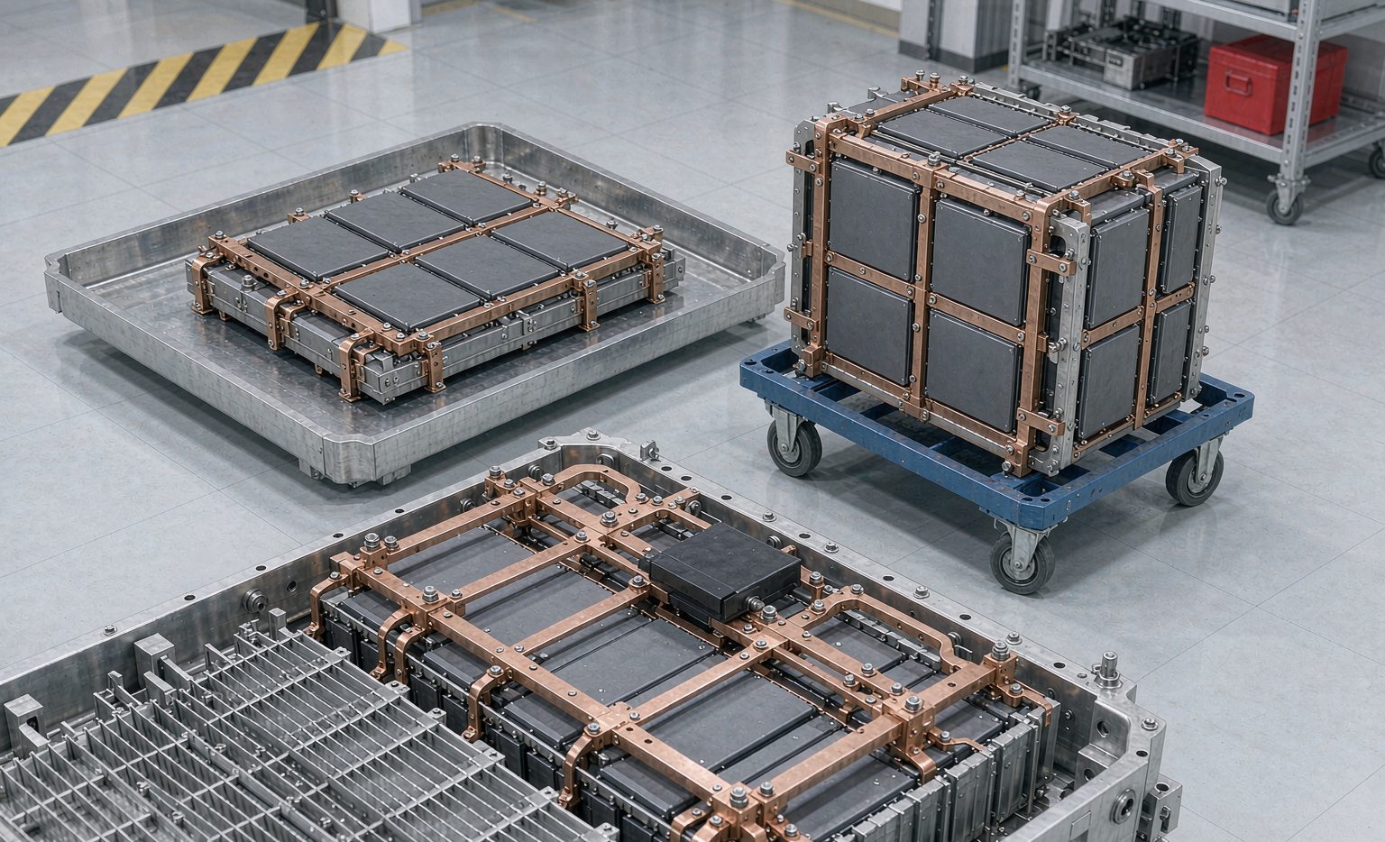
Electrical integration is where small numbers matter. Every series joint adds resistance and, with it, heat. For semi-solid packs running sustained 1-3 C discharge into an 800 V architecture, I target a joint resistance below 0.15 mΩ per busbar connection and I verify it with a four-wire Kelvin measurement on 100% of production joints. We use ultrasonic welding for the tab-to-busbar interface because it avoids the heat-affected zone you get from resistance spot welding, and we map the weld with Cpk ≥ 1.67 on peel strength.
Busbar sizing is driven by the continuous current, not the peak. For a 150 kW front drive unit pulling through a 400 V pack, the continuous conductor sees roughly 375 A; I derate copper at 4 A/mm² for the thermal envelope and then add 20% because semi-solid cells tolerate fast discharge with less voltage sag, which tempts designers to size conductors too thin. The busbar layout also sets your pack’s short-circuit let-through, so we pair it with a-rated fuse sized to clear at 18-22 kA.
This is the same discipline I apply when configuring a high-rate drone battery: the cell can deliver the amps, but the pack only delivers what the weakest joint allows.
Thermal Integration: Coupling Cells to the Cooling Plate
Semi-solid cells run cooler than NMC at equivalent power, but they are unforgiving of thermal gradient. I design for a temperature spread of less than 5 °C across the pack because uneven aging is what kills a pack’s usable capacity years before the warranty ends. The cooling plate uses a water-glycol loop (50/50 by volume) with a thermal interface material in the 2-5 W/mK range, and I set the cold-plate face velocity at 0.8-1.2 m/s to balance pump power against gradient.
One detail that surprises newcomers: the thermal pad is also a structural bond, so its compression must be consistent to within ±10%. If one cell sees 1.5 mm of pad and its neighbor sees 2.0 mm, you get a 1-2 °C gradient that the BMS cannot fix because it only sees thermistor points, not the cell surface between them. We fixture the gap on the line and audit it with a laser profilometer.
On the safety side, the enclosure gets a mica layer of 0.3-0.5 mm plus 1-2 mm of aerogel at <0.05 W/mK between the cell stack and any passenger-facing surface. That buys the thermal runaway propagation delay the standards now expect, and it is the same reasoning we use in aerospace and drone battery packs where a single cell failure must not cascade.
BMS and Sensing Integration
A semi-solid pack needs more sensing than a liquid-electrolyte pack, not less, because the failure mode is quieter. I integrate cell taps with a measurement accuracy better than ±2 mV and add at least two temperature points per 8-12 cells. The BMS must close the contactor pre-charge at 100 Ω / 200 W to limit inrush below 10 A, and it must run insulation monitoring at ≥ 1 MΩ at 500 VDC with a ground-fault trip at 30 mA within 300 ms.
State of charge estimation is where semi-solid helps: the open-circuit-voltage curve is flatter than LFP but more stable than NMC, so a good model holds SoC within ±2%. I still fuse voltage, current integration, and cell impedance because no single signal survives a cold-soak at -20 °C. For fleets, I push the cell impedance trend to the cloud so we can flag a weakening cell months before it trips a threshold.
Sealing, IP Rating, and Mechanical Validation
The pack lives under a vehicle, so ingress protection is non-negotiable. I target IP67 for the enclosure and validate it with a 30-minute submersion at 1 m after the mechanical shock sequence, not before, because the shock is what opens seams. The vent path is designed to relieve at 0.5-1.5 bar and route gas away from the cabin. Crush resistance is checked at 13 kN over a 75 mm-radius platen per GB 38031 and ECE R100, the two standards I lean on for EV packs alongside IEC 62133-2 and IEC 62619 for the cell and system safety basis.
For any program that also touches aviation or has a sister drone battery line, I keep UN38.3 T.1-T.8 in the test plan from day one so the pack certification does not become a late surprise. FAA and EASA expectations are converging on the same physics, and designing once for both saves a re-spin.
Scaling Integration to the Production Line
The part junior engineers underestimate is that integration must be repeatable, not just correct on the bench. I translate every target above into a line check: four-wire resistance on 100% of joints, laser profilometry on the thermal gap, compression force logging on every stack, and a leak test on every enclosure. The goal is Cpk ≥ 1.67 on the parameters that drive safety and life, because a pack that is perfect in the lab and scattered on the line is a recall waiting to happen.
When a customer asks for a custom battery solution built on semi-solid cells, I tell them up front that 60% of the engineering budget is integration, not cells. That is the honest number, and it is also where a good lithium battery partner separates from a great one. We typically run a 10-16 week integration validation before volume, and I would rather spend that time than explain a field failure later.
Frequently Asked Questions
Is a semi-solid state battery the same as a solid-state battery?
No. A semi-solid state battery uses a partially solid electrolyte with enough liquid to keep ionic conductivity in the useful 1-10 mS/cm range, which makes manufacturing far closer to today’s lithium battery lines. A true solid-state battery removes the liquid entirely and is still mostly pre-production. Semi-solid is the pragmatic bridge.
Can I reuse an existing NMC pack enclosure for semi-solid cells?
Rarely. Different swelling, compression, and thermal behavior mean the mechanical stack and cooling plate usually need re-derivation. I almost always design a custom battery solution from the cell outward rather than retrofit a legacy pack.
What joint resistance should I target on the busbars?
Below 0.15 mΩ per connection, verified with four-wire Kelvin measurement on 100% of production joints and controlled to Cpk ≥ 1.67. Higher resistance quietly robs you of the energy-density advantage.
How tight does the pack temperature spread need to be?
Under 5 °C across the pack. I achieve it with a 2-5 W/mK thermal interface, 0.8-1.2 m/s cold-plate face velocity, and a tightly controlled thermal-pad gap audited on the line.
Which standards cover semi-solid EV pack integration?
The same family as liquid-electrolyte packs: UN38.3 T.1-T.8, IEC 62133-2, IEC 62619, GB 38031, ECE R100, and UL 2580. Aviation-linked or drone battery programs add FAA and EASA alignment through UN38.3.
Integration is the discipline that turns a promising semi-solid state battery cell into a pack a vehicle program can actually build and warranty. Get the bonding, the joints, and the thermal coupling right, hold them on the production line, and the chemistry’s advantage shows up where it matters: in the range and life the customer experiences.