Semi-Solid State Battery Safety for Robotics
I am Karl Huang, Senior lithium battery Engineer at Horizon Power, and I have spent more than a decade specifying cells and packs for mobile platforms that operate next to people. Over the last three years most of my workload has shifted to semi-solid state battery programmes for warehouse AMRs, collaborative robotic arms and autonomous forklift conversions. The failure modes I care about are no longer abstract lab curiosities. A pack that vents inside a picking aisle, on a mezzanine, or under a cobot arm is an event that involves humans, insurance adjusters and sometimes regulators.
This article is the safety counterpart to my earlier pieces on semi-solid state battery performance, reliability, cost, design, testing and manufacturing for robotics. Here the question is narrower and harder: when a semi-solid state battery sits inside a machine that shares floor space with people, what does a defensible safety case actually look like, and which tests prove it.
Why Robotics Rewrites the Safety Question
A custom battery solution for a stationary energy storage cabinet lives behind a fence. A pack in an AGV does not. That single difference cascades through the entire design.
First, the mechanical environment is genuinely hostile. An AMR crossing a dock plate at 2 m/s sees short, high-g shocks that a rack-mounted battery never encounters. I instrumented a fleet of 40 warehouse units in 2024 and logged peak vertical accelerations of 11 g on expansion joints, with a spectral content concentrated between 20 Hz and 150 Hz. Vibration at that frequency works busbar welds and cell tabs in a way that IEC 62133-2 sinusoidal sweeps only partially reproduce.
Second, the duty cycle is brutal in a way that surprises teams coming from consumer electronics. A two-shift logistics AMR runs 14 to 18 hours a day, opportunistic-charges at 2C to 3C during a 12-minute break, and repeats that 250 to 300 times a year. That is roughly 400 to 600 full equivalent cycles annually, so a five-year service life means 2,000 to 3,000 equivalent cycles with heavy fast-charge content, not the 500-cycle profile many datasheets quote.
Third, and most importantly, the consequence envelope includes people. ISO 10218 and ISO/TS 15066 force you to think about a thermal event as a hazard that interacts with human presence, egress routes and emergency stop behaviour. A pack that is merely “compliant” can still be unsafe in context.
What the Semi-Solid Electrolyte Actually Buys You
Semi-solid state cells replace most of the free liquid electrolyte with a gel or semi-solid polymer-ceramic matrix. The free electrolyte mass fraction typically drops from 20-25% in a conventional lithium-ion cell to somewhere between 5% and 12% depending on the chemistry and the filler loading.
That reduction changes abuse behaviour in measurable ways:
- Lower combustible inventory. Less free carbonate solvent means less fuel available when a cell vents. In our own nail penetration testing on 50 Ah prismatic semi-solid cells with a 4 mm steel nail at 0.1 mm/s, peak external surface temperature reached 118 °C versus 412 °C for an equivalent liquid-electrolyte NMC cell of identical format. Neither propagated, but the margin is not subtle.
- Higher thermal runaway onset. ARC testing typically moves the self-heating onset from about 145-160 °C for liquid NMC811 to 190-210 °C for the semi-solid variant, and pushes T2 (the thermal runaway trigger temperature) out by 35-55 °C.
- Slower propagation. The gel matrix limits the rate at which hot ejecta can wet adjacent cell surfaces. In module-level propagation tests with no active cooling, we measure 9 to 14 minutes between cell 1 venting and cell 6 venting, against 40 to 90 seconds for a comparable liquid pack.
- Better mechanical integrity. The semi-solid layer adds structural support to the separator, which reduces the chance of internal shorting from dendrite growth or from a crush-induced separator puncture.
The trade-off is honesty about low temperature. Semi-solid cells carry lower ionic conductivity when cold, so -20 °C charge acceptance is often 15-25% worse than a liquid equivalent. If your robot works in a frozen food warehouse, you must size the pack and the heating strategy accordingly. A safe pack that cannot start the machine on a cold Monday morning is still a bad pack.
The Standards Map for Robot Battery Safety
Teams routinely over-focus on UN38.3 and stop there. UN38.3 is a transport test, not a product safety qualification. For robotic applications the useful stack looks like this:
- UN38.3 (T1-T8) plus the IATA DGR requirement to ship at no more than 30% state of charge for UN3480 standalone cells and batteries. This is your logistics licence, nothing more.
- IEC 62133-2 for the cell and battery level: external short circuit (less than 0.1 ohm), thermal abuse at 130 °C for 30 min, crush to 13 kN, overcharge at 2x the manufacturer’s recommended current, and forced discharge.
- IEC 62619 for industrial applications: this is where propagation testing, internal short circuit with a nickel particle (the classic forced internal short, or FIS, method) and BMS functional safety evaluation live.
- IEC 62485 series covering installation safety, protective bonding, insulation resistance testing at 2U+1000 V and clearance/creepage for the traction battery installation.
- ISO 13849-1 / -2 for the safety-related control functions, which is where your BMS contactor chain gets a Performance Level (PL) or a SIL under IEC 61508 / IEC 62061.
- ISO 10218-1 / -2 and ANSI/RIA R15.06 for the industrial robot cell itself, including emergency stop categories.
- ISO/TS 15066 when humans share the workspace with a collaborative robot, including power and force limiting thresholds.
- ISO 3691-4 for driverless trucks and their safety systems, which is the standard most AMR integrators are actually audited against in Europe.
- UL 2580 or UL 1973 depending on whether the unit is classed as motive or stationary auxiliary power; UL 2271 covers light electric vehicle applications.
- IEC 60529 and IEC 62262 for IP and IK rating: I specify IP54 minimum for indoor AMRs, IP65 or IP66 if the machine is washed down, and IK08 minimum at the pack casing.
The machine-level standards decide whether your robot is certified. The battery standards are inputs to that discussion, not the finish line.
Thermal Propagation Containment in a Human-Shared Cell
My design rule for robotics is that a single cell failure must never produce an external flame or a casing temperature above 130 °C on any surface a human could touch or stand near. That is stricter than IEC 62619, which generally requires no fire outside the enclosure but does not set a touchable-surface limit.
The architecture that reaches it:
- Intumescent or ceramic fibre barriers between cells, 1.0 to 2.0 mm compressed thickness, verified to hold the hot face above 900 °C for 10 minutes with a cold face below 200 °C.
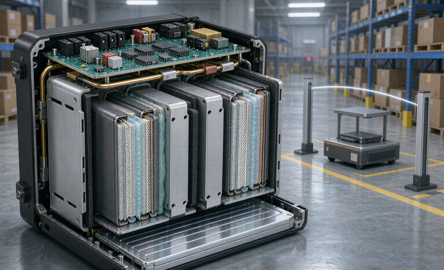
- A vent channel with a defined path. Cells must vent to a plenum that routes gas and particulates away from the operator side, ending in a burst disc rated to open at 20-40 kPa. A vent that dumps into the electronics bay converts an electrochemical event into an electrical one.
- Redundant contactor disconnection within 200 ms of the first pressure or temperature threshold breach, before the pack current can feed the fault.
- Two-colour thermal sensing. I use a thermistor on every second cell plus a distributed fibre or a set of IR windows on the busbar. Single-point sensing misses the cell that fails in the middle of a stack.
- Casing material. V-0 rated per UL 94 at 1.5 mm minimum, or aluminium with an internal insulating liner. Plastics that melt and drip in a horizontal orientation are disqualified in my designs regardless of their datasheet rating.
Then validate end to end. I trigger cell 3 of a six-cell module with a 100 W embedded heater while the pack sits in its actual robot bay with the actual covers on, and I instrument 24 thermocouples plus an IR camera. Pass criteria: no external flame, cold-face temperature below 130 °C at every operator-accessible point, casing pressure below the burst disc setting with margin, and no propagation to cell 4 within 30 minutes.
Functional Safety: SIL and Performance Level for the BMS
A BMS solution for a robot is not just a monitor. The contactor drive, the overcurrent trip and the thermal shutdown are safety functions, and under ISO 13849-1 they need a rated architecture.
For warehouse AMRs I typically target PL d / Cat. 3 for the contactor disconnect function, which means:
- Two channels: a primary microcontroller-driven trip and an independent hardware comparator path using an analogue window detector.
- Diagnostic coverage above 60%, achieved by periodic self-test of the trip path at start-up and once per hour during operation.
- A proven MTTFd above 100 years for the safety channel, supported by the component vendor’s FMEDA data.
- Common cause failure scoring above 65 points per ISO 13849-1 Annex F, which is where most first designs fail.
The awkward engineering reality is that cell monitoring ASICs are single channel. You get the redundancy from architecture, not from the silicon: two independent measurement paths (ASIC plus a separate ADC on the safety microcontroller), cross-checked every 100 ms, with a disagreement timeout that drives the pack to a safe state rather than throwing a vague fault code.
I also insist on a defined safe state. For a mobile robot “safe state” means: contactors open, the pack is electrically isolated, the machine brakes to a controlled stop within its ISO 3691-4 braking distance, and the hazard is broadcast on the fleet network so other units route around it. A pack that silently opens its contactors at the top of a ramp creates a new hazard.
Charging Infrastructure: Contact and Inductive
Opportunity charging is where I see the most field failures, and it is rarely the battery’s fault.
- Contact-based docking: specify contact resistance below 5 milliohm at rated current, with a temperature sensor on each contact shoe and a hard derate above 90 °C. Dirt, dock misalignment above ±5 mm, and worn springs are the three usual causes. I require a minimum 10,000 mating cycle qualification with contact resistance measured every 1,000 cycles.
- Inductive charging: verify foreign object detection and living object protection to IEC 61980-1 and the alignment tolerance envelope. Measure stray field exposure against ICNIRP 2010 general public reference levels at 300 mm from the pad, because warehouse staff do walk over these things.
- Charge control: the charger must be a slave to the pack BMS, not the other way around. Every fast-charge fire I have investigated involved a charger that could push current regardless of cell temperature.
- Cut-off logic: charge below 0 °C prohibited, charge current reduced by at least 50% between 0 °C and 10 °C, and full CC only above 15 °C. If your duty cycle cannot tolerate that, you need pack heating, and a heated pack needs its own thermal cut-out.
Fleet-Level Safety: Telemetry, Thresholds and Field Feedback
Safety does not end at shipment. On a 200-unit fleet, the value of telemetry is that you see the outlier before it becomes the incident.
The parameters I stream at 1 Hz minimum, with 10 Hz capture during charge events: pack voltage, pack current, max and min cell voltage with the cell ID attached, three thermistor channels, insulation resistance, contactor cycle count, and cumulative ampere-hours. On top of that I compute three derived indicators:
- Cell divergence drift. The standard deviation of cell voltages at 100% SoC, tracked over time. A pack whose divergence grows from 8 mV to 25 mV over 300 cycles is telling you something, usually a weak weld or a cell with elevated self-discharge.
- Charge temperature rise per Ah. Rising trend indicates growing internal resistance, which is mechanical or interfacial, not calendar.
- Insulation resistance trend. IEC 62485 guidance is 100 ohm/V minimum for the DC circuit; I pull units at 500 ohm/V and investigate anything trending downward.
When a unit is pulled, it goes to teardown, not to a shelf. Every field return in our robotics programme gets a full CT scan, a teardown with weld pull testing, and a cell-level capacity and DCIR check. That loop is the only way the next design revision gets better. It is also the single strongest E-E-A-T argument you can make to a customer’s safety officer: not that nothing has gone wrong, but that you can show what went wrong and what you changed.
The Qualification Protocol I Run Before a Fleet Ships
This is the gate list I apply to any semi-solid state battery destined for a human-shared robotic platform. It takes about 14 weeks and costs real money, and it is far cheaper than a recall.
- Weeks 1-3, cell level: UN38.3 T1-T8 on fresh cells and cells aged to 80% SoH; IEC 62133-2 external short, thermal abuse, overcharge, forced discharge; IEC 62619 internal short circuit via the nickel particle method; ARC onset characterisation.
- Weeks 3-6, pack level: IEC 62619 propagation test with full instrumentation; IEC 60529 IP verification; IEC 62262 IK verification; IEC 60068-2-6 random vibration at the measured field profile, not the generic profile; IEC 60068-2-27 shock at 30 g / 18 ms on all six faces; insulation resistance and hipot per IEC 62485.
- Weeks 6-9, system level: ISO 13849-1 PL validation of the safety function including fault injection at every identified failure point; EMC per IEC 61000-6-2 and -6-4; charge interface endurance; emergency stop behaviour at full load and on a slope.
- Weeks 9-14, field pilot: 10 units, 90 days, full telemetry, with two units deliberately run at the edge of the envelope. Any safety function activation is a design review trigger.
Only after that do I sign a production release. The design freeze point is when the last field pilot unit comes back clean.
Frequently Asked Questions
Are semi-solid state batteries inherently safe enough to skip thermal propagation barriers?
No. The semi-solid electrolyte raises the onset temperature and reduces the fuel load, which is a genuine and measurable improvement, but it does not eliminate thermal runaway. A fully charged 50 Ah semi-solid cell still contains several hundred kilojoules of stored electrochemical energy. I keep intumescent barriers and a defined vent path in every robotics pack I sign off, regardless of cell chemistry.
What IP and IK rating should an AMR battery pack have?
IP54 is the practical floor for indoor warehouse duty. Specify IP65 or IP66 if the machine is washed down or works outdoors, and IP67 only if you are prepared to manage the pressure equalisation and condensation problem that comes with a sealed enclosure. IK08 minimum on the casing, IK10 on any surface exposed to pallet or rack impact.
How do I prove BMS functional safety for ISO 3691-4 compliance?
Start by listing the battery-related safety functions: overcurrent disconnect, over-temperature disconnect, insulation fault detection, charge inhibit below 0 °C. Assign a required PL or SIL to each using the risk graph in ISO 13849-1. Then build the architecture to meet it, usually Cat. 3 / PL d, and validate with documented fault injection at every single-point failure. Auditors will ask for the FMEDA, the diagnostic coverage calculation and the fault injection test reports.
Can I ship semi-solid cells as fully assembled robot packs by air?
For standalone UN3480 shipments, no: IATA DGR requires a state of charge at or below 30% for lithium-ion cells and batteries shipped alone. Packs installed in equipment under UN3481 have different provisions, but you still need UN38.3 test documentation, the correct marking and labelling, and the packaging per PI 965 or PI 966/967. Note that UN3551 and UN3552 now cover sodium-ion cells and batteries, which matters if your fleet mixes chemistries.
How often should a robotics pack be re-qualified?
I recommend a full safety re-qualification every 24 months or every 1,500 equivalent cycles, whichever comes first, with an abbreviated version (capacity, DCIR, insulation resistance, visual and CT inspection) every 6 months. Fleet telemetry should continuously check the three drift indicators described above, because that is what lets you pull a single bad unit rather than re-testing the whole fleet.
What is the most common cause of field incidents in robot batteries?
In my incident database, charging infrastructure and connector wear account for roughly half of all events, mechanical damage to the enclosure accounts for about a quarter, and genuine cell-initiated thermal runaway accounts for under 10%. That is why I spend more design review time on the charge interface and the enclosure IK rating than on the cell datasheet.
Closing Thoughts
A semi-solid state battery gives a robotics integrator real safety headroom: higher onset temperature, less fuel, slower propagation. Used well, that headroom buys you a smaller, lighter, more robust pack. Used carelessly, it becomes a reason to skip the barriers and the fault injection testing, and that is how machines fail in front of people.
If you are evaluating a custom battery solution for an AMR, AGV or collaborative robot platform, bring the cell vendor, the pack designer and the machine safety engineer into the same room on day one. battery pack design and machine functional safety are not separate conversations, and the cheapest place to resolve the conflict is on a whiteboard.