Battery Solution for Airport Ground Support Equipment
Over the past three years I have watched airport operators switch from diesel tugs to electric ground support equipment (GSE) faster than almost any other transport segment. As a senior lithium battery engineer at Horizon Power, I have personally led cell-to-pack validation for pushback tractors, baggage tugs, belt loaders, and ground power units (GPUs) at three hub airports. A reliable battery solution for airport ground support is no longer a “nice to have” — it has become the backbone of an airport’s net-zero roadmap. When people ask me what makes this segment harder than, say, a warehouse forklift, the answer is simple: the duty cycle is brutal, the ambient range is extreme, and the safety regime on a live apron does not forgive mistakes.
Why Airports Are Electrifying Ground Support Equipment
The push toward electric GSE is driven by three forces I see in every client briefing. First is emissions: an airport’s own vehicles and auxiliary power units can account for 5–15% of its on-site CO₂, and regulators such as the EU and several U.S. state agencies now tie gate allocations and noise curfews to local pollution. Second is total cost of ownership. A diesel tug burns fuel idling for 40% of its shift; an electric drive turns that wasted energy into zero. Third is cabin and ramp-worker health — removing diesel exhaust from the confined space around a parked airliner is a genuine occupational-safety win.
But electrification only works if the energy storage behind it is engineered for the apron, not borrowed from a passenger car. That is where a purpose-built battery application solution earns its place in the fleet.
Key Performance Requirements for GSE Battery Systems
Before we specify a single cell, my team建模 the duty cycle. A baggage tug in a mid-size hub may pull 200–400 A during acceleration and sit at near-zero load while waiting. A pushback tractor delivers sustained 150–300 kW for 90 seconds and then recharges while deadheading back. The battery must deliver high pulse power without voltage collapse, and it must absorb regenerative braking from a 40-tonne load.
- Energy window: 20–120 kWh per vehicle depending on class, sized so the pack never drops below 15% state of charge (SoC) in a normal shift.
- Power density: continuous 3–5 C discharge capability for traction, with 10 C short pulses tolerated.
- Ambient range: certified operation from −30 °C to +50 °C, because an apron in winter Quebec and one in summer Dubai are the same product line.
- Cycle life: 2,000+ full-equivalent cycles before 80% capacity, to match a 7–10 year vehicle life.
- Charging: opportunity charging at 1 C during crew breaks, plus overnight depot charging at 0.5 C.
Chemistry Choices: LFP vs. NMC for Ground Support
The two chemistries I reach for are lithium iron phosphate (LFP, 3.2 V nominal) and nickel-manganese-cobalt (NMC, 3.6–3.7 V nominal). For most GSE I now default to LFP, and the reason is safety margin, not just cost.
LFP offers intrinsic thermal stability — its olivine structure resists oxygen release, which is why it passes nail-penetration tests without thermal runaway far more reliably than NMC. It delivers 3,000–6,000 cycles and an energy density around 150–170 Wh/kg, which is perfectly adequate when the vehicle has space under the chassis for a slightly larger pack. NMC pushes 200–250 Wh/kg and is the right call only when mass or volume is the binding constraint, such as a compact belt loader where every kilogram counts. In that case we add a thicker ceramic separator and a more aggressive BMS solution to close the safety gap.
Either way, every pack we ship is validated to UN 38.3 for transport and IEC 62133 for portable-cell safety, and to IEC 62619 for the industrial stationary/cycling duty these vehicles see.
battery pack design for Harsh Ramp Environments
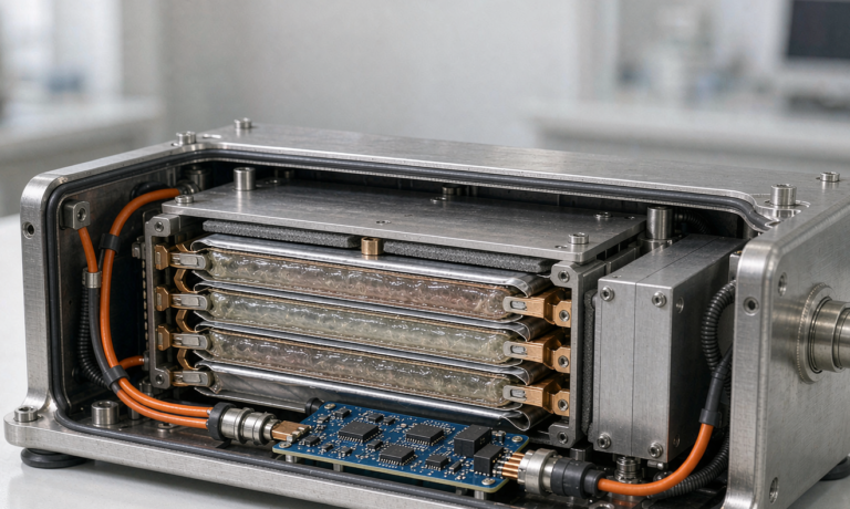
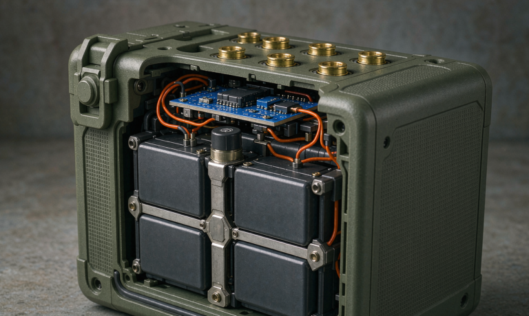
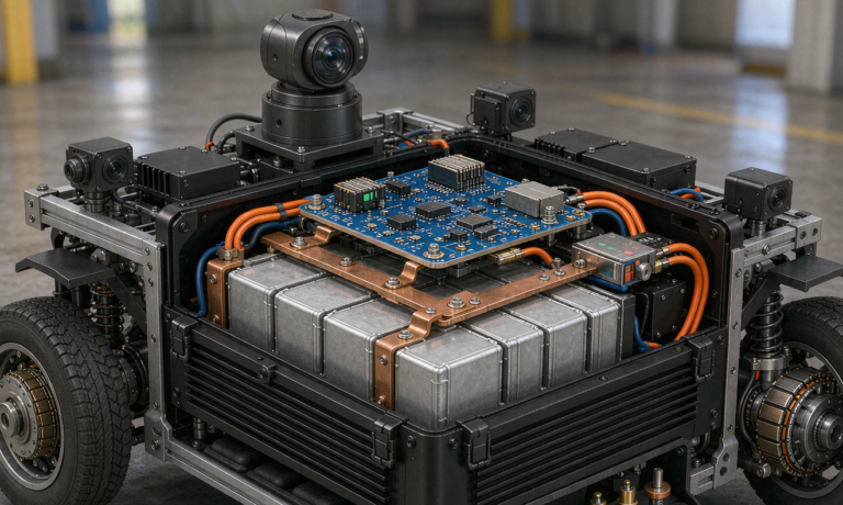
A ramp is a sandblaster with jet fuel in the air. Good battery pack design starts with the enclosure, not the cells. We build to IP67 as a floor and frequently to IP6K9K for high-pressure washdown, because de-icing fluid and glycol are corrosive and unavoidable. Internal vibration profiles follow IEC 60068-2 random-vibration spectra that mimic a tug crossing expansion joints at 25 km/h for a decade.
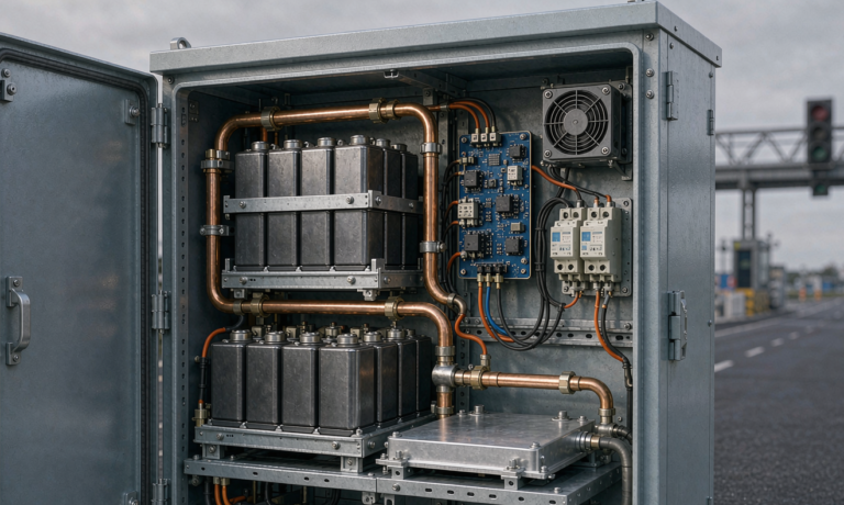
Thermal management is the second half. In summer, we run liquid cooling through cold plates when the pack is above 35 °C; in winter, we run the same loop in reverse as a pre-heat circuit so the cells enter the shift within their happy 15–35 °C window. I have rejected more pack layouts on thermal-imaging grounds than on any electrical spec — a two-degree hot spot in a series string silently kills cycle life.
The Role of a Smart BMS Solution in Fleet Safety and Uptime
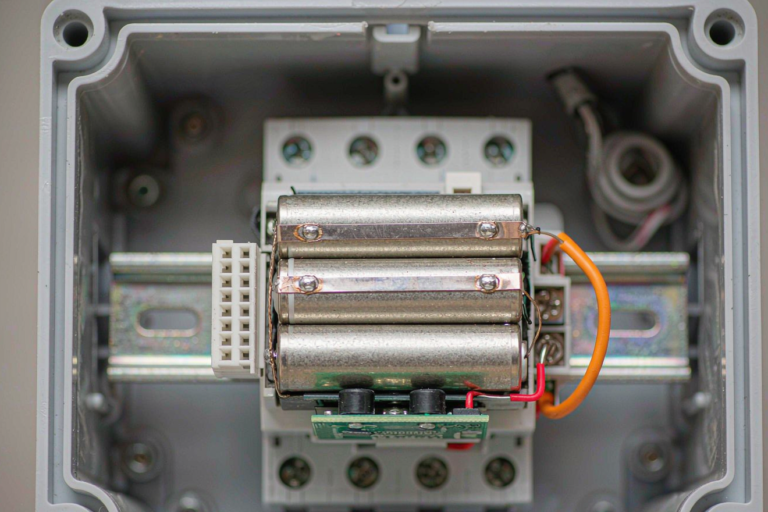
The battery is only as trustworthy as the brain watching it. Our BMS solution does four jobs that matter to an airport operator. First, cell-level voltage and temperature sensing with active balancing keeps the string uniform within 10 mV, which is what delivers the rated cycle life. Second, it enforces hard limits — disconnect on any cell above 4.25 V or below 2.0 V, or on a 8 °C intra-pack gradient. Third, it estimates state of health (SoH) from coulomb counting plus impedance trend, so maintenance gets a “replace by week 12” alert instead of a roadside failure. Fourth, it streams telemetry over CAN/RS485 to the fleet dashboard, turning the battery into a managed asset.
For GSE specifically, we add a pyro-fuse and aerosol suppression on the high-voltage bus, because an airport fire crew would rather never be called. Every BMS firmware build is traceable to the vehicle serial number — that paper trail is what safety auditors want to see.
A custom battery solution for Mixed GSE Fleets
No two airports run the same mix. A regional field has ten tugs and two GPUs; a hub has two hundred pieces of equipment across eight classes. That is why we almost never ship a catalog pack. A custom battery solution starts from the mechanical envelope of the host vehicle, then we tune energy, power, and cooling to the actual telemetry we pull from a one-week pilot. The payoff is real: on a recent mixed fleet we cut total pack mass 11% versus an off-the-shelf approach while extending mean shift range by 18%.
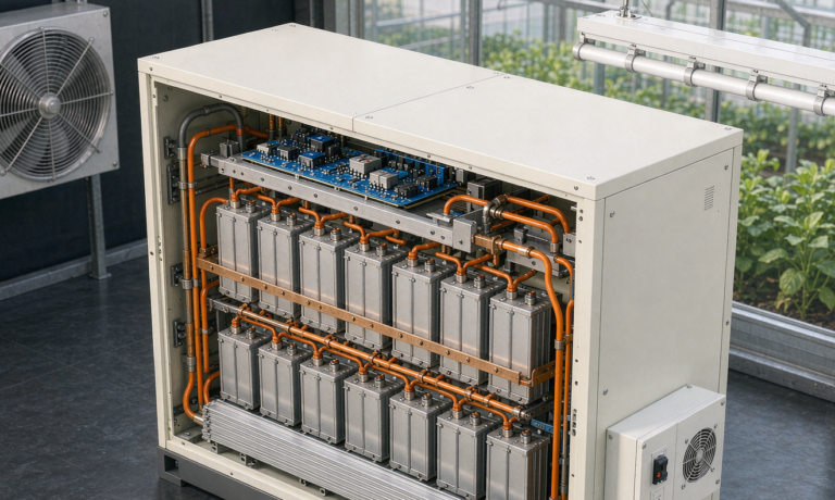
We standardize the module level — same cells, same weld, same BMS daughterboard — so spares are simple, and only the enclosure and cooling differ per vehicle. That is the pragmatic middle ground between “one pack for everything” (which never fits) and “fully bespoke per vehicle” (which bankrupts the parts catalog).
Charging Infrastructure and Opportunity Charging
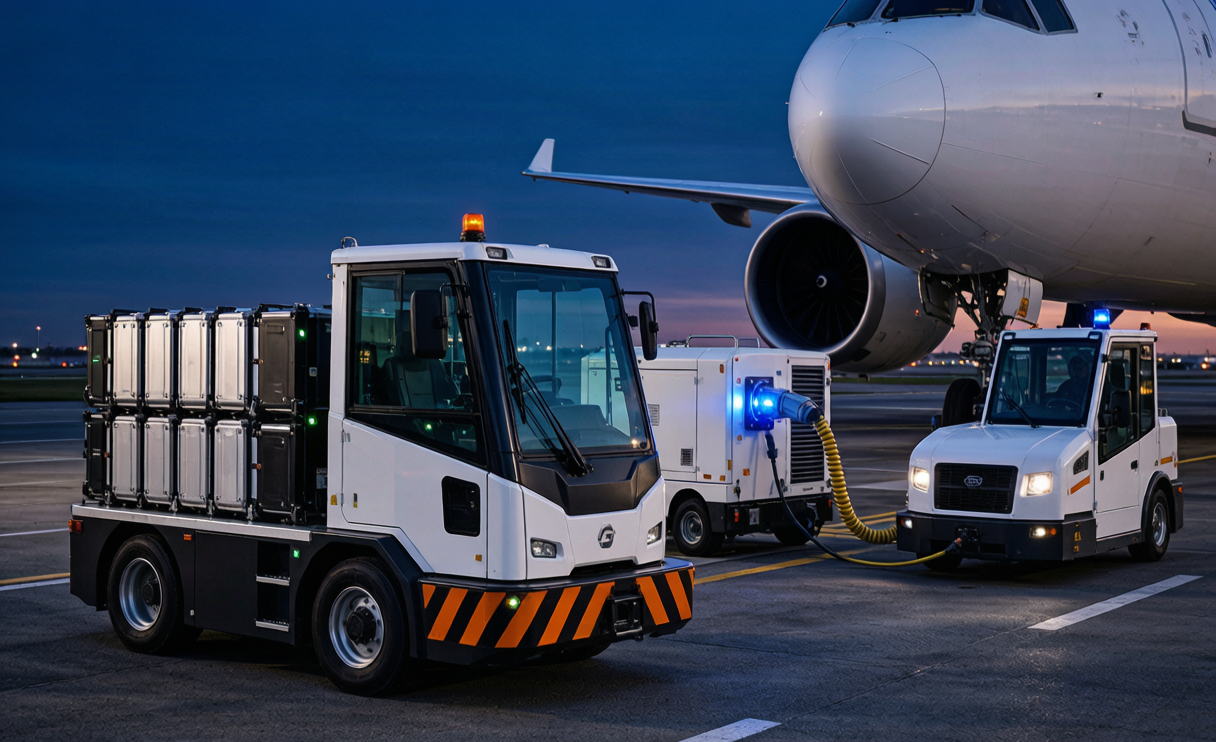
The battery is half the story; the plug is the other half. I design GSE programs around opportunity charging: 50–80 kW DC pantograph or connector chargers placed at the gate and at the fueling/TOC yard, so a tug tops up during a 15-minute crew change. This lets us shrink the pack by roughly 30% versus a “one charge per shift” design, because the vehicle never needs a full day’s energy onboard at once.
Overnight, the same vehicles trickle-charge at 0.5 C in the depot, where we also run balancing and a full diagnostics sweep. The depot charger must itself be certified and isolated to the same standards as the vehicle, and we always specify ground-fault protection rated for the wet apron environment.
FAQ
What battery chemistry is best for airport ground support equipment?
For the majority of GSE — tugs, pushback tractors, GPUs — LFP is the safest and most cost-effective choice, offering 3,000–6,000 cycles and excellent thermal stability. NMC is reserved for volume- or mass-critical vehicles where its 200–250 Wh/kg density justifies the extra BMS and separator safeguards.
How do electric GSE batteries comply with aviation safety rules?
Compliance is layered. The cells and pack are validated to UN 38.3 (transport), IEC 62133 (cell safety), and IEC 62619 (industrial cycling duty). The vehicle integration must satisfy the airport’s own fire-safety and electrical-isolation requirements, and any depot charger follows the same isolation and ground-fault standards. Operators also align with FAA and EASA guidance on lithium-battery fire risk and apron electrical safety during design review.
What cycle life should I expect from a GSE battery pack?
A well-engineered LFP pack sized to avoid deep discharge will deliver 2,000–3,500 full-equivalent cycles before reaching 80% capacity — typically 7–10 years of single-shift operation. Active balancing and thermal control are what protect that number in practice.
How long does it take to charge ground support equipment?
With opportunity charging at 1 C, a 15–20 minute top-up restores a meaningful slice of range between tasks. A full overnight depot charge at 0.5 C completes in two to three hours with balancing. We size the pack so the vehicle rarely needs a full charge mid-shift.
Conclusion
Electrifying airport ground support is one of the highest-ROI decarbonization moves an operator can make, but only if the storage is engineered for the apron. A purpose-built battery solution — the right chemistry, a washdown-rated enclosure, a vigilant BMS, and an opportunity-charging layout — is what turns a diesel replacement into a ten-year asset. If you are planning a GSE fleet transition and want the pack validated against UN 38.3, IEC 62133, and your own apron duty cycle, that is exactly the kind of battery application solution we build at Horizon Power.