Home Energy Storage Battery Balancing Method: An Engineer’s Field Guide
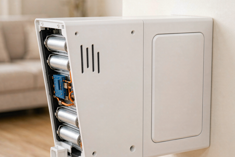
I have spent fifteen years with a multimeter in one hand and a thermal camera in the other, chasing the same stubborn failure mode across hundreds of packs: cell drift. Whether it is a 6S drone battery pulling 120 A on takeoff or a 48 V home energy storage wall unit cycling gently every evening, the physics do not change. Cells age at slightly different rates, their state of charge diverges, and unless something pulls them back into line, the weakest cell dictates the usable capacity of the entire pack. In residential storage, where the customer expects a decade of service from a five-figure asset, the home energy storage battery balancing method you choose is not a footnote in the BMS datasheet. It is the design decision that separates a system still delivering 85 percent of nameplate capacity in year ten from one that quietly loses a fifth of its usable energy by year four.
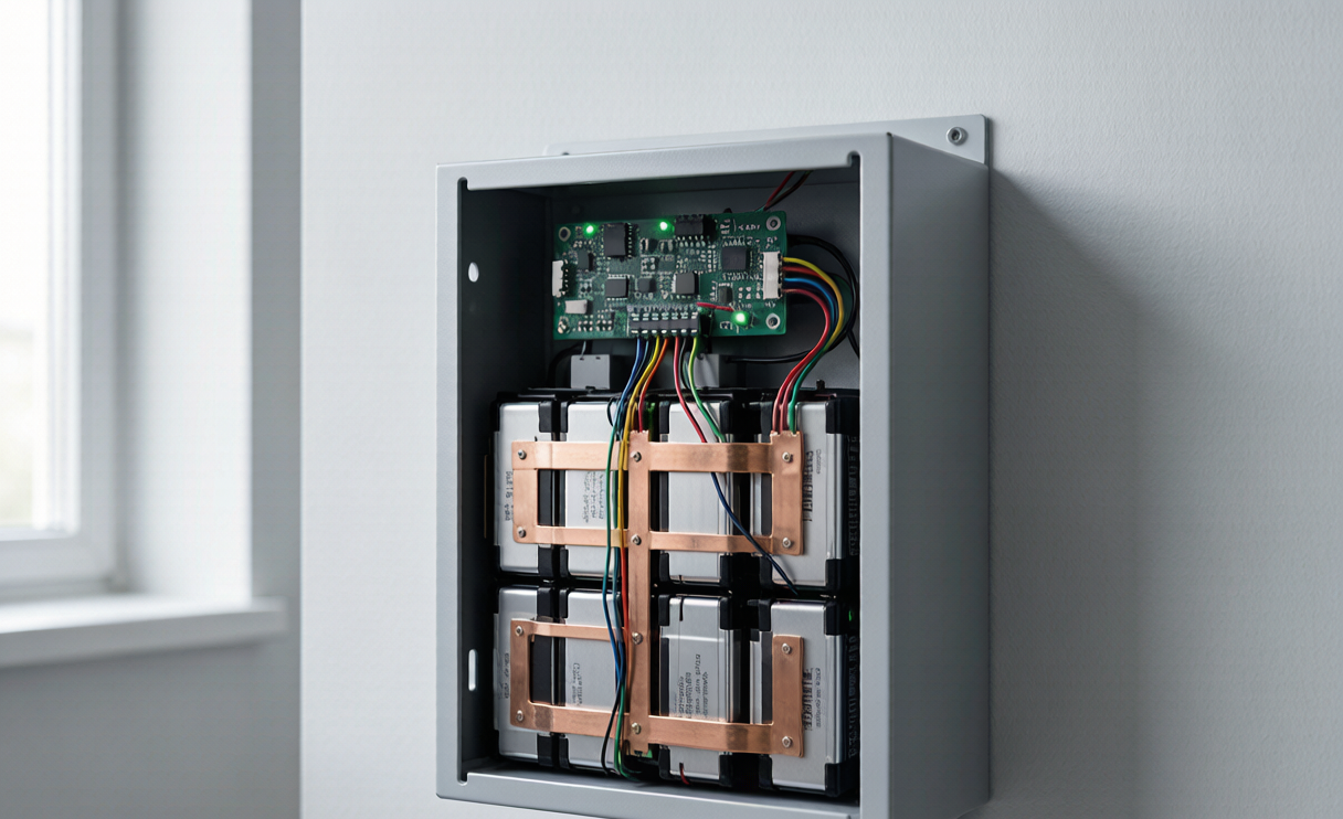
This guide covers what balancing does at the cell level, the trade-offs between passive and active topologies, how to size balancing current for a real residential pack, and the field diagnostics I use when a customer calls to say their battery “lost capacity.” The numbers come from packs I have personally commissioned, and the standards referenced — IEC 62619, UL 1973, IEC 62133-2, UN 38.3 — are the ones that govern how these systems must behave when things go wrong.
Why Cells Drift in the First Place
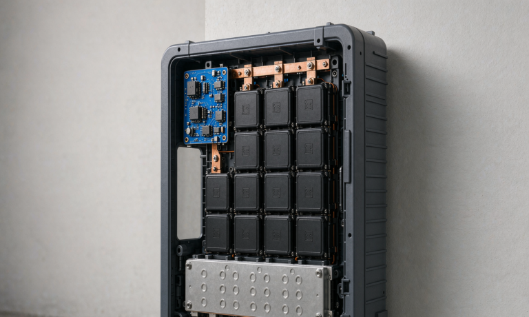
A home energy storage pack is a series string — a typical 48 V LiFePO4 wall unit is 16 cells in series (16S) at 3.2 V nominal each, while high-voltage stacks run 48S to 60S for a 150–200 V DC bus feeding a hybrid inverter. Every cell in a string sees identical current. What is not identical is how each cell responds to it. Three mechanisms drive divergence:
- Manufacturing tolerance. Even grade-A cells from a single lot arrive with capacity spread. On incoming inspection I typically measure 1–2 percent capacity variation on a 280 Ah LiFePO4 cell — 3 to 6 Ah between the best and worst cell in a box of sixteen. Internal resistance spread is wider, 5–10 percent at 1 kHz AC impedance.
- Self-discharge asymmetry. The quiet killer. A healthy LiFePO4 cell self-discharges 2–3 percent per month at 25 °C; one with a marginal separator or trace metallic contamination might do 5 percent. Over a year standing partially charged, that differential alone opens a 10 percent SOC gap.
- Thermal gradients. In a wall-mounted cabinet, cells near the center of the stack run 4–8 °C hotter than end cells under 0.5C charge. Arrhenius kinetics being what they are, every 10 °C rise roughly doubles calendar aging. Center cells wear out faster.
The consequence is unforgiving. On charge, the highest-SOC cell hits the 3.65 V cutoff first and the BMS terminates charging for the whole string, leaving every other cell short of full. On discharge, the lowest-SOC cell hits 2.5 V first and discharge stops. Usable capacity collapses to the span between those constraints. I have measured a 16S 280 Ah pack with 12 percent SOC spread delivering only 231 Ah usable — an 18 percent loss with no actual cell degradation whatsoever.
Passive Balancing: The Workhorse of Residential Storage
Passive (dissipative) balancing is the method in perhaps 90 percent of residential lithium battery systems shipping today. Each cell tap connects through a MOSFET to a bleed resistor; when the BMS sees a cell above the string average, it switches that resistor in and burns off the excess as heat until the cell falls back into line.
The appeal is obvious: cheap, simple, and very little to go wrong. A passive balancer adds perhaps two dollars of BOM cost per cell channel, with no inductors, transformers, or complex switching control loop.
The limitation is balancing current. Standard residential BMS boards deliver 50 mA to 200 mA per channel; premium units reach 300 mA. That sounds workable until you run the arithmetic. Moving 5 Ah out of an over-charged cell at 100 mA takes 50 hours of continuous balancing — but the BMS only balances near the top of the charge curve, typically 30–60 minutes per cycle. At 100 mA for 45 minutes you move 75 mAh. Correcting a 5 Ah imbalance therefore takes about 67 cycles, more than two months of daily solar cycling.
The second constraint is thermal. A 200 mA bleed at 3.5 V dissipates 0.7 W per channel. Balance eight channels in a sealed enclosure and you add 5.6 W of heat directly onto the cell stack — on packs I have instrumented, that raises local cell temperature 3–5 °C. Manageable, but precisely the wrong direction: you are heating the cells that are already hottest.
My rule for passive balancing in home storage: it works well if, and only if, the pack was properly top-balanced at commissioning and the cells were matched at build. It is a maintenance tool for slow drift, not a recovery tool for a badly assembled pack.
Active Balancing: Moving Charge Instead of Burning It
Active balancing transfers energy from high cells to low cells rather than dissipating it. Three topologies dominate:
Capacitive (Switched-Capacitor) Transfer
A flying capacitor is switched across a high cell, charges, then switches across an adjacent lower cell and dumps its charge. Elegantly simple and reasonably efficient — 85 to 92 percent in units I have bench-tested. The drawback is that transfer only happens between adjacent cells, so moving charge from cell 1 to cell 16 cascades through fourteen hops. Equalization across a long string is slow.
Inductive / Transformer-Based Transfer
An inductor or multi-winding transformer moves energy from any cell to the pack bus, or from the bus down to any cell. This is the topology I specify for high-value residential and light commercial systems. Balancing currents of 1 A to 5 A are routine, and because transfer is any-to-any, correcting a 5 Ah imbalance at 2 A takes 2.5 hours instead of two months. Efficiency runs 80 to 90 percent. Cost is the trade: expect 8 to 20 dollars per channel of added BOM, plus board area and more complex control firmware.
DC-DC Converter Per Cell
The premium approach — an isolated bidirectional converter on every cell. Fully independent, very fast, and it enables genuinely useful features like keeping a weak cell in service by continuously feeding it. I mostly see this in grid-scale applications; for a residential wall unit it is difficult to justify against the incremental energy recovered.
The honest engineering assessment I give customers: for a well-built pack with matched cells, active balancing recovers maybe 3 to 6 percent of usable capacity over the system’s life compared to good passive balancing. For a pack with mixed-vintage or poorly matched cells, it can recover 15 to 25 percent. The value of active balancing is inversely proportional to the quality of cell matching at build. This is why, when we engineer a custom battery solution for a residential OEM, I push the budget toward cell matching first and active balancing second.
Top-Balancing vs. Bottom-Balancing: Getting Commissioning Right
This is where I see the most field failures, and it is entirely avoidable. Balancing must be anchored at a reference point on the SOC curve, and for LiFePO4 the choice matters enormously because the chemistry has an extraordinarily flat voltage plateau — roughly 3.20 to 3.35 V across 20 to 90 percent SOC. In that region a 10 mV measurement error corresponds to about 8 percent SOC error. Voltage-based balancing in the plateau is essentially guesswork.
Top-balancing brings every cell to the same high-SOC voltage, typically 3.60–3.65 V, where the curve rises steeply and voltage is a meaningful SOC proxy. This is correct for home energy storage: these systems live near the top of the charge window and the critical safety constraint is preventing individual cell overvoltage during solar absorption.
Bottom-balancing aligns cells around 2.50–2.80 V, protecting the weakest cell against over-discharge. That matters in applications that routinely run the pack flat — a drone battery on an endurance mission fits that profile. For residential storage, where depth of discharge is usually capped at 80–90 percent by inverter configuration, top-balancing is the right call.
My commissioning procedure for a new 16S residential pack:
- Charge every cell individually to 3.65 V at 0.05C on a bench supply in constant-voltage mode, holding until current tapers below 0.01C. That takes 12–18 hours for 280 Ah cells and cannot be rushed.
- Rest 4 hours and record open-circuit voltage. Any cell sagging more than 15 mV below the group is a self-discharge flag and goes back for investigation.
- Assemble the string, torque busbars to the cell manufacturer’s spec (typically 4–6 N·m for M6 prismatic terminals) and verify each joint under 50 µΩ with a micro-ohmmeter.
- Run three full cycles at 0.2C with BMS logging, then review per-cell delta-V at end of charge. A well-commissioned pack shows under 20 mV spread at 3.65 V.
That last figure is my acceptance criterion. Under 20 mV spread at handover, passive balancing will hold the pack for years. At 60 mV, no balancing method ever fully catches up.
Standards, Safety, and What the Certifications Actually Require
Balancing is not just a performance feature — it is a safety function, and certification treats it that way:
- IEC 62619 — safety for secondary lithium cells in industrial and stationary storage. It mandates that the BMS prevent any cell from exceeding manufacturer voltage limits, and sustained imbalance is the primary mechanism that pushes a cell past that limit.
- UL 1973 — the North American stationary battery standard. It requires demonstrated overcharge protection at the cell level, not just pack level, putting your balancing and cell-monitoring architecture directly in scope.
- IEC 62133-2 — cell-level safety baseline that most cell suppliers certify against. Ask your vendor to produce it before anything enters a pack.
- UN 38.3 — transport qualification, tests T.1 through T.8 covering altitude, thermal cycling, vibration, shock, short circuit, impact, overcharge, and forced discharge. The T.7 overcharge test is precisely where inadequate balancing reveals itself.
- UL 9540A — thermal runaway propagation characterization, increasingly requested by AHJs for indoor or garage-mounted residential units.
The regulatory logic is consistent: the standards do not prescribe a balancing topology, they prescribe an outcome — no cell shall exceed its safe operating window under any foreseeable condition. If you choose 50 mA passive balancing for a pack with 8 percent cell spread, you have chosen a system that cannot meet that outcome, and a competent test lab will find it.
Field Diagnostics: Reading a Pack That Has Gone Out of Balance
When a customer reports capacity loss, I work through the same four steps, which resolve the question remotely in under an hour most of the time.
- Pull the delta-V log at end of charge — the value at the moment the BMS terminated charge, not the instantaneous reading. Under 30 mV is healthy; 30–80 mV means the balancer is losing ground; above 100 mV means genuine cell degradation.
- Single outlier or general spread? One cell sitting 150 mV above the pack is a low-capacity or high-resistance cell — it fills faster because it holds less. Spread across many cells points to inadequate balancing current or a commissioning failure.
- Is the imbalance symmetric? Log cell voltages at both ends of the cycle. If the same cell is highest at the top and lowest at the bottom, it has reduced capacity. High at both ends means a simple SOC offset that balancing will correct.
- Thermal imaging under load. A cell running 5 °C above its neighbours at 0.5C discharge has elevated internal resistance, is heading for failure, and no balancing method will save it. Combined with capacity data, that justifies a warranty replacement.
One case stays with me: a 48 V 200 Ah unit reported at 60 percent of rated capacity after eighteen months, with 180 mV spread at end of charge. The installer assumed cell failure, but thermal imaging showed all cells within 1.5 °C. The pack had simply never been top-balanced at commissioning — assembled from cells at differing states of charge straight out of the box, and the 80 mA passive balancer never had a chance. We top-balanced every cell over two days, reassembled, and it returned to 97 percent of rated capacity. Most “capacity loss” in residential lithium battery packs during the first three years is unbalance, not degradation.
Choosing the Right Balancing Architecture for Your Product
When a client asks us to develop a custom battery solution for residential storage, the balancing specification falls out of three questions:
- Cell matching budget. Cells matched to within 1 percent capacity and 5 percent internal resistance need only 100–200 mA passive balancing; spend the savings on thermal management. Unmatched or mixed-lot cells require active balancing at 1 A minimum — and will still underperform.
- Duty cycle. A pack cycling daily on solar self-consumption gets a balancing window every day and accumulates correction steadily. A backup-only pack sitting at float for months gets almost none, so it needs active balancing or a scheduled monthly maintenance charge.
- String length. A 16S 48 V pack is forgiving. A 48S stack has three times the opportunities for drift and three times the cells that can individually terminate charge — above roughly 24S I specify active balancing by default. The principle scales down too: in a compact 6S drone lithium battery, where every gram matters, we compensate with tight cell matching because there is no room for a balancing transformer.
The through-line — from a home energy storage wall unit to an industrial pack to a drone battery — is that balancing is a system property, not a component you bolt on. It emerges from cell selection, thermal design, commissioning discipline, and BMS capability working together.
Frequently Asked Questions
How much balancing current does a home energy storage battery actually need?
Size it against expected drift: required balancing current equals expected annual capacity divergence divided by annual balancing hours available. For a 280 Ah pack with 2 percent annual divergence, that is 5.6 Ah per year. Daily cycling gives roughly 45 minutes of balancing window per cycle, or 274 hours annually — about 20 mA required. So 100 mA passive is comfortably adequate for a well-matched pack. Double the divergence for mixed-quality cells and halve the window for backup duty, and you need 80 mA sustained average, which in practice means specifying 300 mA or moving to active balancing.
Can I add an active balancer to an existing home battery system?
Physically yes — standalone modules connect to existing cell taps and operate independently of the main BMS. Two cautions. Adding a second device to the voltage-sense harness introduces a parallel current path and, if the balancer fails short, a potential cell-discharge fault. It will also likely void the manufacturer’s warranty and may invalidate the UL 1973 or IEC 62619 listing, which creates real problems with your insurer or AHJ. If the pack is out of warranty and you accept the risk, use a module with proper fusing on every sense lead. Otherwise do a manual top-balance instead.
Is balancing different for LiFePO4 compared to NMC in home storage?
Meaningfully, yes. NMC has a sloped voltage curve, so cell voltage stays a reasonable SOC indicator across most of the range and voltage-based balancing works throughout the cycle. LiFePO4’s flat plateau means balancing decisions are only reliable near the top or bottom, compressing the useful window to the tail end of charge. This is why LiFePO4 systems benefit disproportionately from coulomb-counting BMS firmware that tracks accumulated charge per cell. Ask any prospective supplier whether their balancing algorithm is voltage-triggered or SOC-model-driven — the answer says a lot about the engineering behind the product.
How often should a home energy storage pack be manually rebalanced?
For a properly commissioned, daily-cycling system with working passive balancing, never — the BMS should hold it indefinitely. Review end-of-charge delta-V annually from the logs; if it has grown beyond 50 mV year over year, intervene. For backup-duty systems sitting at float, program a full absorption charge to 3.60 V per cell held for four hours once per quarter.
What delta-V should I see on a healthy pack?
At end of charge, under 30 mV across all cells in a LiFePO4 residential pack. Mid-plateau readings are not diagnostically useful because the curve is flat — a 5 mV spread at 3.30 V tells you nothing. At end of discharge, under 50 mV is acceptable. If you track one number, track end-of-charge delta-V, and watch its trend year over year rather than its value on any given day.