Battery Solution for Unmanned Surface Vessels: An Engineer’s Field Guide
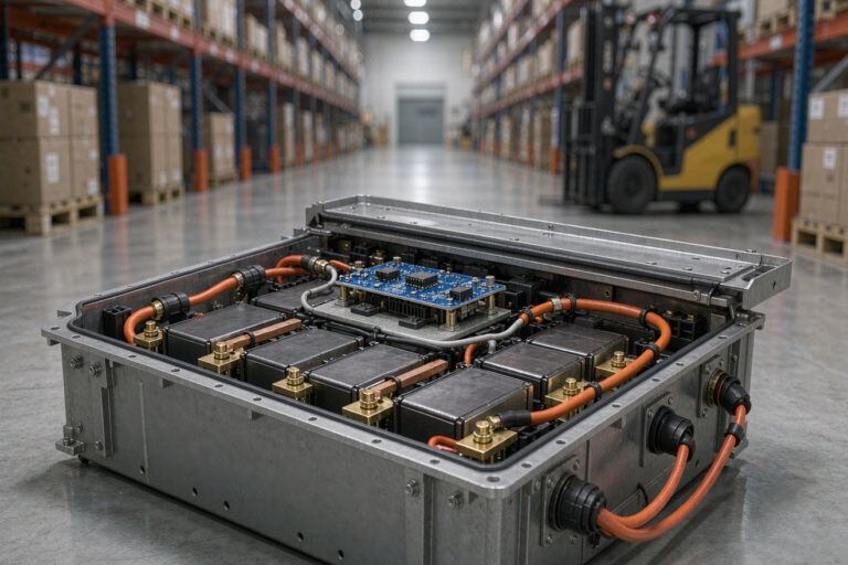
The first unmanned surface vessel programme I supported lost three boats in a single survey season. Not to collision, not to grounding, but to water finding its way into battery enclosures that everyone on the project had signed off as sealed. I flew to the harbour in Zhoushan, opened the returned packs on a folding table, and found the same story in each one: salt crystals on the busbars, green corrosion creeping across the balance connector, and a BMS board whose conformal coating had been scratched during assembly. That week reshaped how I design every marine pack I have built since.
A battery solution for an unmanned surface vessel is not a drone battery scaled up, and it is not a stationary storage cabinet made smaller. It sits in a punishing middle ground: continuous vibration, salt fog, condensation cycling, wide temperature swings, unattended operation for days, and no human on board to notice the smell of a cell going wrong. This guide covers how I specify, build and validate those packs.
Why Unmanned Surface Vessel Power Is Its Own Engineering Problem
Aerial platforms optimise for gravimetric energy density because every gram costs flight time. Surface vessels do not care nearly as much about mass — buoyancy is free. What they care about is runtime, survivability and the ability to sit in a wet, corrosive environment for years. That single difference cascades through every design decision, from cell chemistry to connector selection.
Mission profiles also look nothing alike. A survey drone boat may run eight to twenty hours at a modest cruise load, then spike to three or four times that current when it fights a tidal current or manoeuvres against wind. Hydrographic vessels towing sonar arrays add a near-constant hotel load for payload electronics. I plan for a duty cycle, not a peak number, and I always ask for logged current traces from any previous hull before quoting a pack.
The third distinguishing factor is recovery cost. When a multirotor’s lithium battery fails, the aircraft falls a hundred metres. When an unmanned surface vessel loses propulsion twelve nautical miles offshore, you are chartering a boat, burning a day, and hoping the hull is still where the last GPS ping said it was. That asymmetry justifies redundancy that would be unthinkable on an airborne platform.
Choosing Cell Chemistry for Marine Autonomy
For most unmanned surface vessels I specify LiFePO4 (LFP) prismatic or large-format cylindrical cells. The energy density penalty versus NMC — roughly 150 to 175 Wh/kg at cell level against 230 to 270 Wh/kg — is acceptable when the hull can carry the mass. What you buy in exchange is thermal runaway onset above 200 degrees Celsius rather than around 150 degrees Celsius, cycle life of 3,000 to 6,000 cycles at 80 percent depth of discharge, and far more forgiving behaviour if a cell is over-discharged during an extended drift.
NMC still earns its place on high-speed interceptor or long-endurance craft where displacement is tightly constrained. In those builds I accept the chemistry but tighten everything around it: cell-level fusing, mandatory thermal barriers between modules, and a BMS that will open the contactor on a 3 degrees Celsius intercell delta rather than waiting for an absolute limit.
Semi-solid-state cells have started appearing in marine prototypes I have evaluated. Their reduced liquid electrolyte content improves puncture and thermal tolerance meaningfully, and I expect them to become the default for premium unmanned vessels within a few years. Today the supply chain and cost still push most production programmes back toward LFP, but I now build enclosure geometry that can accept either format so a customer’s next refresh is a module swap rather than a redesign.
Sealing, Corrosion and Pressure Management
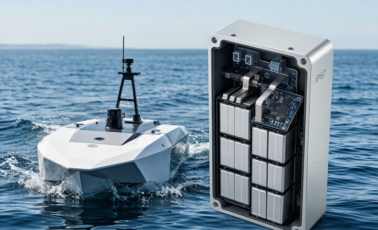
Ingress protection is where marine packs are won or lost. I target IEC 60529 IP67 as an absolute floor and IP68 for any pack mounted below the waterline or in a compartment that can flood. But an IP rating on a datasheet is a test result, not a guarantee across five years of thermal cycling — gaskets take compression set, and screws back off under vibration.
Three practices have eliminated almost all the water ingress I used to see. First, a Gore-type pressure equalisation vent on every enclosure. Sealed boxes breathe as they heat and cool; without a vent membrane, the pack draws humid air past its gasket every night and condenses it inside. Second, marine-grade connectors rated IP68 when mated and IP67 when capped, with gold-plated contacts rather than tin. Third, full conformal coating on the BMS with careful masking, inspected under UV before the lid goes on.
Galvanic corrosion deserves its own review. Anodised aluminium enclosures with stainless fasteners will corrode at the interface in salt spray unless you isolate them — I use nylon shoulder washers and a dielectric compound at every dissimilar-metal joint. Salt fog testing to ASTM B117 for 500 hours catches material pairings that look fine on a CAD screen.
BMS Architecture for Unattended Operation
Nobody is aboard to reset a tripped protection. That reality drives the biggest architectural difference between a marine BMS and the one in a typical lithium battery pack: it must fail into a recoverable state, not a bricked one.
I design for graceful degradation. When a single string faults, the vessel should not go dark — it should drop to reduced power and continue toward the recovery waypoint. That means parallel strings with ideal-diode or contactor-based isolation, each independently monitored, and a supervisory controller that reports pack health over the vessel’s CAN bus or NMEA 2000 network at least once a second.
Practical thresholds I use on LFP marine packs: cell overvoltage cutoff 3.65 V with a 3.55 V warning, undervoltage cutoff 2.5 V with a 2.8 V limp-home trigger, charge inhibit below 0 degrees Celsius, discharge derate above 55 degrees Celsius, and intercell delta alarm at 60 mV. Every one of those events gets timestamped in non-volatile memory. When a boat comes home misbehaving, that log is the difference between a two-hour diagnosis and a two-week argument.
State-of-charge accuracy matters more than operators expect. LFP’s flat voltage plateau makes voltage-based estimation nearly useless between 20 and 90 percent, so I always pair coulomb counting with periodic full-charge recalibration and temperature-compensated internal resistance tracking. A vessel that thinks it has 30 percent remaining when it actually has 12 percent is a vessel you will be recovering.
Certification, Transport and Regulatory Compliance
Every marine pack we ship passes UN 38.3 testing — T.1 altitude simulation through T.8 forced discharge — because the pack has to travel to the customer before it ever touches water. For packs above 100 Wh, which covers essentially all unmanned surface vessel batteries, air freight falls under IATA Packing Instruction 965 or 966 depending on whether cells ship standalone or installed, and most large marine packs move by sea under IMDG Class 9 UN3480 or UN3481 instead.
On the product safety side I hold cells and packs to IEC 62133-2:2017 and, for the larger multi-kilowatt-hour systems, IEC 62619 for industrial secondary lithium batteries. Vessels operating commercially in classed service may additionally need to satisfy classification society requirements — DNV, ABS or Lloyd’s Register all publish lithium battery rules for marine installations, and those typically demand gas detection, dedicated ventilation and documented thermal runaway propagation testing.
Vibration and shock validation follows IEC 60068-2-6 and 2-27 as a baseline, though for planing hulls that slam I prefer MIL-STD-810H Method 514.8 profiles. A hull hitting waves at 25 knots imposes repeated shocks that will find every under-torqued busbar you shipped.
Building a custom battery solution That Survives Deployment
A production-ready custom battery solution starts with a written mission profile, not a voltage and capacity. I ask for six things: nominal and peak propulsion current, hotel load, required endurance with reserve, ambient water and air temperature range, available compartment volume and access, and charge infrastructure at the dock. Half the programmes I see have never written those down, and the specification exercise alone usually surfaces a contradiction worth fixing before any metal is cut.
Modularity pays for itself. I standardise on modules a single technician can lift and swap through a deck hatch — generally in the 15 to 25 kilogram range — rather than one monolithic pack. When a module fails at a remote base, the vessel is back on task in twenty minutes. Consistent module interfaces also mean the same pack architecture that powers a survey vessel can be adapted into the drone battery line or a shore-side charging buffer with minimal requalification.
Finally, instrument everything and read the data. On every fleet I support, we pull BMS logs monthly and track capacity fade, resistance growth and temperature distribution per module. That trend line is how you retire a pack before it strands a boat, and it is the single highest-return habit any unmanned vessel operator can adopt.
Frequently Asked Questions
What battery capacity does an unmanned surface vessel typically need?
It varies enormously with hull and mission. Small inspection craft under three metres often run 2 to 5 kWh for six to ten hours of survey work. Mid-size hydrographic vessels of five to eight metres typically carry 15 to 40 kWh. Long-endurance autonomous platforms with solar assist may use 50 kWh or more. Always size from a logged duty cycle with at least 25 percent reserve, not from a cruise-speed average.
Is LFP or NMC better for a marine battery solution?
LFP is the default recommendation for unmanned surface vessels. Its higher thermal runaway threshold, longer cycle life and tolerance of deep discharge outweigh the energy density gap when hull displacement allows. Choose NMC only when the volume or mass budget genuinely forces it, and pair it with stricter thermal management and cell-level fusing.
How do you prevent condensation inside a sealed marine battery pack?
Use a hydrophobic pressure equalisation vent rather than a fully sealed box, keep enclosure internal volume low, apply conformal coating to all electronics, and where the duty cycle is severe add a small desiccant cartridge with an inspection window at each service interval. Sealing alone traps moisture; managed breathing keeps it out.
Can drone battery packs be reused on unmanned surface vessels?
Rarely without modification. A drone lithium battery is optimised for gravimetric density and short high-rate discharge, often with minimal ingress protection and connectors never intended for salt exposure. The cells may be suitable, but the enclosure, sealing, BMS thresholds and connector system all need redesign for marine service.
How long should a marine lithium battery pack last?
A well-designed LFP pack cycled to 80 percent depth of discharge should deliver 3,000 to 5,000 cycles before reaching 80 percent of rated capacity. In practice, calendar ageing and environmental damage usually set the retirement point first. With good sealing and thermal control I expect eight to ten years of service; with poor sealing, I have seen packs fail in eighteen months.
Closing Thoughts
The unmanned surface vessel packs that survive are rarely the ones with the most impressive specification sheet. They are the ones where somebody sweated the vent membrane, the dissimilar-metal joint and the BMS log format. Those details do not photograph well, but they are what keeps a boat coming home.