
Drone Battery Connector and Wiring Harness Selection
I am Karl Huang, Senior lithium battery Engineer at Horizon Power. Over the past decade I have torn down more failed drone power systems than I can count, and I can tell you something that surprises most buyers: the cell chemistry was rarely the problem. In roughly six out of ten field failures I have investigated, the root cause sat in the two centimetres between the pack and the ESC — a scorched connector, a cold solder joint, an undersized wire, or a harness that vibrated its way into an intermittent open circuit. drone battery connector and wiring harness selection is the least glamorous part of pack engineering and the single most common place where good cells are wasted.
This guide is the internal decision framework my team uses when we specify interconnects for a new airframe. It covers the physics of contact resistance, how to match a connector class to your real current envelope, how to size wire without paying a mass penalty, and how we qualify a harness so it survives 500 flights instead of 50. Whether you are integrating an off-the-shelf pack or commissioning a custom battery solution, these are the numbers that matter.
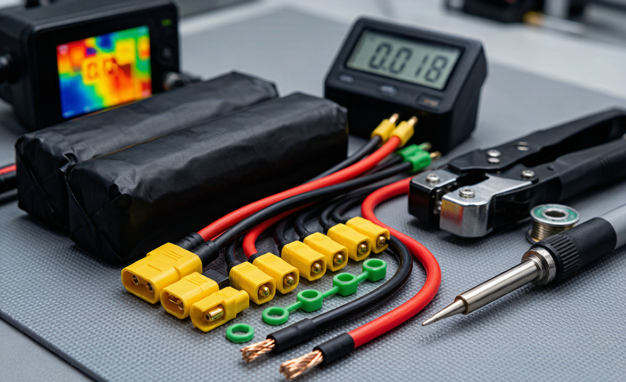
Why the Interconnect Decides Real Flight Performance
A drone battery is a current source with an internal resistance, and every connector, crimp and centimetre of copper you place downstream adds to that resistance. The load does not care where the resistance lives — it only sees the total. On a typical inspection multirotor drawing 100 A in hover, a harness plus connector path of 3 mΩ produces a 0.3 V drop and dissipates 30 W as heat. On a 22.2 V nominal 6S system delivering about 2,200 W, that is roughly 1.4% of your energy converted into warm plastic instead of thrust.
That sounds trivial until you translate it into mission terms. On a 20-minute flight, 1.4% is 15–25 seconds of endurance — often the difference between finishing a survey grid and aborting one waypoint short. Multiply it across a fleet flying three sorties a day and the interconnect quietly costs you flight hours you already paid for in cells.
There is a second, harsher penalty. Resistance is not static. A degraded contact heats, oxidises, and its resistance climbs, which makes it heat more. I have measured connectors that started at 0.25 mΩ and reached 2.5 mΩ after 400 careless mating cycles — a tenfold increase. At 100 A that single contact now dissipates 25 W in a housing rated for maybe 5 W of passive cooling. That is the thermal runaway pathway that melts housings and, in the worst cases, shorts a pack.
The Physics You Must Design Around: I²R, Voltage Drop, and Temperature Rise
Three equations govern every interconnect decision. Power dissipation follows P = I²R, which means current dominates: doubling current quadruples heat. Voltage drop follows V = IR, which is what steals your headroom. And temperature rise is roughly proportional to dissipated power divided by the connector’s thermal conductance to ambient.
Our internal design rules, refined over many airframe programmes:
- Total interconnect resistance target: below 15% of the pack’s own internal resistance. A healthy 6S 22 Ah NMC pack sits around 8–12 mΩ, so we budget 1.2–1.8 mΩ for the entire path from cell tabs to ESC pads.
- Connector temperature rise: no more than 30 K above ambient at continuous rated current, consistent with the derating philosophy in IEC 61984 for connectors. At 45 °C ambient in summer field work, that caps connector body temperature near 75 °C — still below the 105–125 °C limit of common thermoplastic housings.
- Voltage drop budget: under 1.5% of pack nominal at peak continuous current, and under 3% at burst current.
- Peak-to-continuous ratio: we size for the 10-second burst, not the hover average. Aggressive attitude corrections on a heavy platform routinely pull 2–3× hover current.
One measurement discipline matters more than any spec sheet: use a four-wire Kelvin milliohm meter, not a handheld multimeter. A standard DMM cannot resolve sub-milliohm contact resistance, and its own lead resistance swamps the reading. We log a baseline resistance for every new harness and retire any connector whose resistance exceeds twice that baseline.
Matching Connector Class to Your Real Current Envelope
Connector current ratings published by distributors are optimistic because they usually assume a short burst, generous wire, and free air. Here is how the common families behave in real drone service, based on our own bench characterisation:
- 3.5 mm / 4 mm bullet connectors: useful up to roughly 40–70 A continuous per contact when properly soldered to matched wire. Common on motor-to-ESC phase leads rather than main battery leads.
- XT60-class: comfortable to about 45–60 A continuous with 12 AWG, contact resistance typically 0.3–0.6 mΩ when new. Fine for sub-5 kg platforms and small drone lithium battery packs.
- XT90-class: our default for 60–90 A continuous, 0.2–0.3 mΩ new, pairs with 10 AWG. The anti-spark variant with an integral pre-charge resistor is what we specify for anything above 6S.
- EC5 and 5.5–6 mm bullets: 90–120 A continuous territory, suited to heavy-lift and agricultural platforms.
- AS150 / XT150-class: 130–160 A continuous with 8 AWG, reserved for large 12S–14S industrial and cargo airframes where inrush energy is genuinely dangerous.
Plating matters as much as size. Gold-plated contacts over a nickel underlayer hold low, stable resistance for 500–1,000 mating cycles. Bare nickel or tin plating is cheaper but oxidises, and in salt-laden or humid environments I have seen resistance triple within a season. For any pack destined for coastal or offshore duty we specify gold plating and a corrosion-resistant shell, and we treat the connector as a scheduled-replacement wear item rather than a permanent fixture.
A practical warning about mixing families: never rely on adapter dongles as a permanent solution. Each adapter inserts two additional contact pairs and a length of wire, easily adding 1–2 mΩ and a mechanical hinge point that concentrates vibration. If an airframe needs a different interface, the correct answer is a custom drone battery lead terminated to the airframe’s native connector, not a stack of adapters.
Sizing the Harness: Gauge, Strand Count, and Insulation
Wire selection is a three-way trade between resistance, mass, and flexibility. The copper resistances we design with, at 20 °C:
- 14 AWG — 2.08 mm², about 8.3 mΩ/m
- 12 AWG — 3.31 mm², about 5.2 mΩ/m
- 10 AWG — 5.26 mm², about 3.3 mΩ/m
- 8 AWG — 8.37 mm², about 2.1 mΩ/m
Remember to count both conductors. A 150 mm positive lead plus 150 mm negative lead in 10 AWG contributes 2 × 0.15 m × 3.3 mΩ/m ≈ 1.0 mΩ — already most of a tight resistance budget. This is why we obsess over lead length. Shortening a pair of leads from 300 mm to 150 mm on a 100 A platform saves 1 mΩ, 10 W of heat, and about 30 g of copper. Free endurance, no chemistry change required.
Also correct for temperature. Copper resistivity rises roughly 0.39% per kelvin, so a harness at 70 °C carries about 20% more resistance than the datasheet 20 °C figure. We always verify voltage drop at worst-case hot conditions, never at bench ambient.
For insulation, silicone rubber is the only material we accept on main power leads. It is rated to 180–200 °C, stays flexible at −40 °C, and tolerates repeated flexing at the strain relief. PVC insulation, rated near 80–105 °C, stiffens in cold weather and cracks after a season of vibration. High strand counts — 1,000 to 1,650 strands of fine copper for 10 AWG — matter for fatigue life: a coarse-strand wire work-hardens and fractures internally where it enters the connector, producing the intermittent faults that are nearly impossible to diagnose in flight.
Termination Craft: Solder, Crimp, and Strain Relief
The joint is where most harnesses actually fail. Both soldering and crimping can be excellent; both are easy to do badly.
Soldered joints suit bullet and XT-style cups. The failure mode to avoid is solder wicking up the strands beyond the joint, creating a rigid section that becomes a stress riser and cracks under vibration. We control this with a temperature-controlled iron at 380–420 °C, a large thermal mass tip, flux-cored solder, and a dwell short enough that wicking stays under 2 mm. Cold joints are equally dangerous: they look acceptable but carry elevated resistance that heats and eventually opens.
Crimped joints are our preference for production volume because they are repeatable and machine-verifiable. We specify hydraulic or ratcheting dies matched to the terminal, and we validate with destructive pull tests against the tensile targets in IPC/WHMA-A-620 — on the order of 300 N for 12 AWG and above 400 N for 10 AWG. A properly formed crimp shows a symmetric barrel with no bird-caging and no severed strands.
Whatever the method, strain relief is mandatory. Our standard build sequence is: adhesive-lined heat-shrink over the joint, a second layer extending 15–20 mm onto the wire jacket, then a mechanical anchor — a cable tie to a structural member or a potted grommet — within 30 mm of the connector body so that no flight load ever reaches the joint. On airframes subject to RTCA DO-160 or MIL-STD-810 style vibration profiles across roughly 5–2,000 Hz, unanchored leads are the first thing to fail.
Anti-Spark, Pre-Charge, and High-Voltage 12S Architectures
Every ESC input has a capacitor bank, typically 400–2,000 µF on a mid-size platform. When you plug a charged lithium battery into that discharged bank, the inrush current is limited only by loop resistance and can momentarily exceed 500 A. That is the arc you see and hear, and it does three destructive things: it pits and vaporises microscopic amounts of contact plating, it stresses the capacitors, and it injects a voltage transient into the ESC’s logic rail.
The fix is a pre-charge path. An anti-spark connector carries a 10–100 Ω resistor on a leading contact that charges the capacitor bank over a few tens of milliseconds before the main contacts mate. On 12S systems — 44.4 V nominal, up to 50.4 V fully charged — I consider this non-negotiable. Above 50 V, an arc no longer self-extinguishes as readily, and sustained arcing can weld contacts closed. On our 12S and 14S industrial packs the pre-charge circuit and its resistor thermal rating are part of the qualified design, not an accessory.
Higher voltage platforms also reward the interconnect designer. Moving from 6S to 12S at the same power halves the current, which cuts I²R interconnect losses to a quarter and allows a smaller, lighter harness. When a customer asks how to gain endurance without changing cells, raising the voltage platform and shortening the harness is often the cheapest engineering win available.
Qualification, Compliance, and Field Inspection
A harness design is not finished until it has been tested as part of the pack. Our qualification sequence for a new drone battery interconnect:
- Baseline resistance — four-wire measurement of every contact pair and lead, recorded against pack serial number.
- Thermal soak at rated current — 30 minutes at continuous rating with thermocouples on the connector body and crimp barrel, confirming rise stays within 30 K.
- Mating endurance — 500 insertion cycles, then re-measure resistance; we require the increase to stay under 50%.
- Vibration and shock — swept sine and random profiles with the harness installed as flown, followed by continuity and resistance re-check.
- Environmental exposure — humidity and, for marine or coastal programmes, salt-mist exposure per ISO 9227 methodology before re-measurement.
Pack-level compliance still applies to the whole assembly. Cells and packs must pass UN38.3 tests T.1 through T.8 for transport, and we qualify to IEC 62133-2:2017 for lithium systems. Connector housings are selected from families with recognised safety approvals for current and voltage rating. For air transport, IATA rules require shipping at or below 30% state of charge, and passenger-carriage limits of 100 Wh and 160 Wh under FAA and EASA guidance dictate how a fleet’s spare packs are moved. Larger lithium battery shipments travel as UN3480 or UN3481 depending on whether they are packed alone or with equipment.
For daily operations, the field inspection is short and worth doing every single flight: look into the connector for discoloured or pitted contacts, feel for a positive detent on mating, check that heat-shrink is intact with no exposed copper, tug-test the strain relief, and after landing touch the connector body — if it is noticeably hotter than the pack case, something in that joint is wrong. We retire a connector at any sign of melted housing, plating loss, loose contact fit, or resistance above twice baseline.
How We Specify Interconnects for a New Programme
When a customer brings us an airframe, the conversation follows a fixed order. First we establish the electrical envelope: hover current, 10-second burst current, and peak accepted by the ESC. Then the environment: ambient temperature range, humidity, salt exposure, vibration spectrum, and how many times a day the pack will be mated. Then the mechanical constraints: available bay volume, routing path, and how much lead length the airframe genuinely needs. Only then do we choose a connector family, gauge, plating, and termination method.
That order matters because interconnect decisions cascade. A 90 A continuous requirement in a 45 °C desert with 6 mates per day is a different connector from 90 A in a temperate hangar with one mate per week, even though the current is identical. This is precisely why a well-executed custom battery solution outperforms a catalogue pack on the same cells — the copper, contacts and strain relief are designed for the mission rather than for the widest possible market.
Frequently Asked Questions
What connector should I use for a 6S drone battery drawing 80 A?
An XT90-class connector with 10 AWG silicone wire is the right starting point. It provides comfortable headroom at 80 A continuous, contributes roughly 0.2–0.3 mΩ when new, and its anti-spark variant handles capacitor inrush safely. An XT60 would survive briefly but runs hot and degrades quickly at that current.
Is soldering or crimping better for drone battery leads?
Both work when executed correctly. Crimping is more repeatable and better suited to production, provided you use matched dies and verify with pull tests. Soldering is fine for connector cups and prototype work, but you must limit solder wicking to about 2 mm and back it with adhesive heat-shrink strain relief. The failure statistics I see come from poor process control, not from the choice itself.
How much flight time does a bad connector actually cost?
More than most operators expect. A path resistance rising from 1.5 mΩ to 5 mΩ on a 100 A platform adds 0.35 V of drop and 35 W of loss, which on a 20-minute mission is roughly 20–40 seconds of endurance — plus a hot spot that shortens the life of every component near it.
Do I need an anti-spark connector on every drone battery?
On systems at 6S and below with modest capacitor banks, a standard connector is generally acceptable, though you will still see contact wear from arcing. At 8S and above, and on any platform with a large capacitor bank or frequent mating cycles, a pre-charge or anti-spark connector should be treated as mandatory. Above roughly 50 V the arc energy is high enough to weld contacts.
How often should connectors and harnesses be replaced?
Treat them as wear items with condition-based replacement rather than a fixed calendar interval. Our thresholds are resistance above twice the recorded baseline, visible plating loss or pitting, any housing deformation, or a loss of positive mating feel. In heavy fleet service with several mates per day, that typically means connector replacement somewhere between 300 and 800 cycles, with the harness itself often outlasting two sets of contacts.
Can a higher voltage platform reduce harness mass?
Yes, and significantly. Doubling voltage from 6S to 12S halves current for the same power, which cuts conduction losses by a factor of four. That often allows a step down in wire gauge and a smaller connector, saving both mass and cost while running cooler. It is one of the most effective changes available when an operator needs more endurance from the same cell technology.





