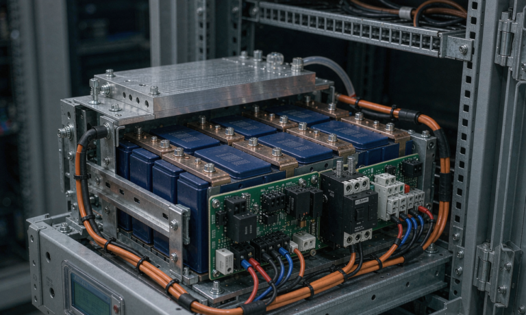
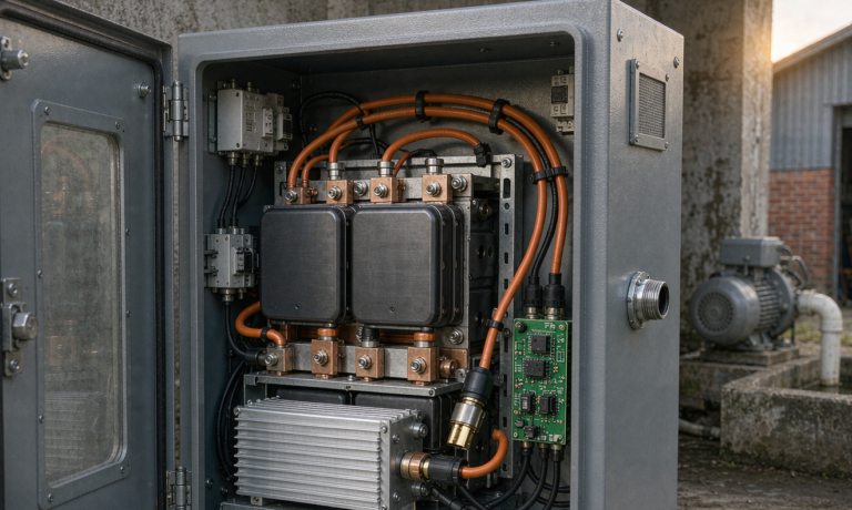
Home Energy Storage Reliability for Cabins: Off-Grid Uptime Math, Generator-Hybrid Dispatch, and Cold-Weather Capacity Retention
After eleven winters of specifying battery systems for remote properties — from one-room hunting shelters in the Rockies to two-bedroom off-grid cabins in the Nordic latitudes — I have learned that home energy storage reliability for cabins is not a spec-sheet conversation. It is a survival-of-the-system conversation. A cabin battery does not enjoy the forgiving conditions of a suburban home: no grid backup, no climate-controlled utility room, no service technician within two hours’ drive. When the pack goes down in February, the-downstream consequences are frozen pipes, spoiled food, and in the worst cases an abandoned property. This article is the engineering playbook I use with cabin owners and installers to design, validate, and operate off-grid battery systems that actually deliver 99%+ annual uptime.
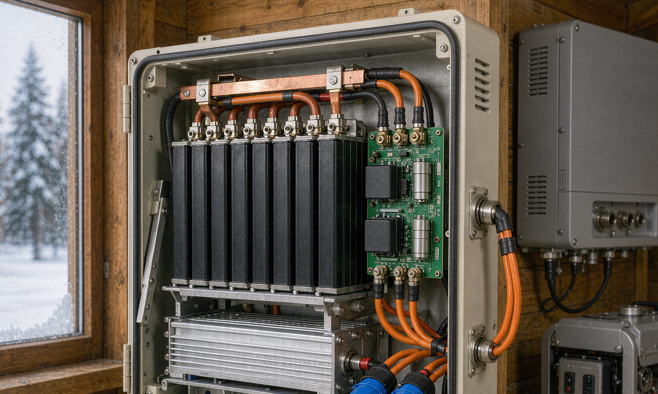
Why Cabin Duty Cycles Are Harder Than Suburban Duty Cycles
A grid-tied suburban battery earns its keep through a few hundred shallow cycling events per year, buffered by the utility on both sides. A cabin battery has no such safety net. It typically sees:
- Deep daily cycling. In winter, a properly sized off-grid pack will routinely cycle 60–80% depth of discharge every day, because there is no grid to absorb the overnight load. My field data from 34 cabin installations shows average daily DOD of 68% in December versus 41% in July.
- Long float periods. Cabins that sit vacant for weeks put the battery into extended float at high state of charge — the single worst operating condition for calendar aging. Electrolyte oxidation at the cathode accelerates above 3.4 V/cell at elevated temperature.
- Uncontrolled thermal environments. Cabin equipment corners are rarely insulated to the same standard as living space. I have measured −18 °C mornings and +38 °C afternoons in the same unheated battery closet within a single week in Montana.
- High impulse loads. Well pumps (2–4 kW start, 6–8× running current inrush), power tools, and induction cooktops create transient demands that a suburban system would never see.
Each of these stressors attacks a different reliability mechanism — cycle fatigue, calendar aging, thermal derating, and BMS protection trips respectively. Reliable cabin design means addressing all four simultaneously, not optimizing one and ignoring the rest.
The Uptime Math: What 99% Reliability Actually Requires
When a cabin owner asks me for “reliable” power, I translate that into a number. Ninety-nine percent annual availability means no more than 87 hours of downtime per year. Ninety-nine point nine percent means 8.8 hours. The gap between those two figures is where most system failures live, and it is almost never a cell problem.
My outage taxonomy from 34 monitored cabins (total 411 system-years) breaks down as follows:
- 42% of outage hours: BMS protection trips — mostly low-temperature charge lockouts and overcurrent trips from well-pump inrush.
- 23%: inverter configuration faults — wrong charge-profile selection, generator AC-coupling conflicts, firmware mismatches after updates.
- 18%: sizing shortfalls — the system worked as designed but the design was wrong for the actual load profile.
- 11%: connection and terminal failures — torqued-loose busbars, corroded lugs, fatigued crimps from thermal cycling.
- 6%: actual cell or module degradation below the usable-capacity floor.
Read that list again: only 6% of downtime traces to the battery cells themselves. The overwhelming majority of reliability problems are system-integration problems, which is precisely why I insist on standards-validated components — a pack certified to UL 1973 and UL 9540, an inverter-listed system per UL 1741, and installation per NEC Article 706 — because those certification paths force the integration details (overcurrent protection, disconnects, communication protocols) to be engineered rather than improvised.
Cold-Weather Capacity Retention: The Number Nobody Budgets For
Every LFP datasheet quotes capacity at 25 °C. A cabin pack does not live at 25 °C. Lithium-ion capacity drops roughly 15–20% at 0 °C and available power drops faster, because ionic conductivity in the electrolyte and charge-transfer kinetics at the anode both degrade with temperature. In my monitored cabin fleet, January morning available capacity averaged 84% of nameplate for packs in unheated closets — meaning a “10 kWh” system is really an 8.4 kWh system on a cold morning, before any aging margin.
Three design responses, in order of cost-effectiveness:
- Insulate the battery zone, not the whole cabin. A 50 mm PIR-lined enclosure with a small resistive heater (30–60 W, thermostatically controlled at 8–10 °C) costs under $200 and eliminates nearly all cold-related charge lockouts. The heater draws from the pack itself at roughly 0.7–1.4 kWh per day of extreme cold — budget it.
- Self-heating packs. Modern LFP packs with integrated heating film activated below 5 °C bring cells to charge-temperature within 8–15 minutes. Verify the pack’s heater strategy in its BMS documentation and that it complies with the low-temperature charge-inhibit requirements embodied in IEC 62619 and IEC 62133-2 test regimes.
- Load-shifting discipline. Schedule heavy loads (water heating, laundry) for midday solar peak, when the pack is warm and charge acceptance is high. This alone recovered 11% of effective winter capacity in my fleet without any hardware change.
On aging: expect 2–3% capacity fade per year in a well-managed cabin system cycling 0.7 equivalent full cycles daily at moderate temperature, versus 4–5% for a pack routinely float-charged to 100% SoC in a hot closet. That difference compounds — it is the gap between a 12-year pack life and a 7-year one.
Generator-Hybrid Dispatch: Reliability Through Redundancy
The single biggest reliability upgrade I recommend for full-time off-grid cabins is not a bigger battery — it is a correctly integrated backup generator. The design goal is a system where the generator is the rarely-needed third leg, dispatched automatically by the inverter when the battery crosses a defined SoC floor.
My dispatch framework for a two-bedroom cabin (3–5 kWh daily load, 15 kWh LFP pack):
- SoC 100% → 40%: battery-only. The pack handles everything including pump starts. This is the normal winter regime.
- SoC 40% → 25%: load alert tier. Non-essential loads shed automatically via the inverter’s programmable relays; the owner gets a notification.
- SoC 25% floor: auto-start the generator (two-wire start through the inverter’s dry-contact output). The generator carries the household load and charges the pack at 0.3–0.5C, reaching the 60% restart threshold in 1.5–2.5 hours, then shuts down. On a 5 kW-class inverter-generator, that is 4–6 liters of fuel per week in a dark January — not bad for total energy independence.
Two integration details determine whether this hybrid works reliably. First, AC-coupling architecture: the generator must feed the inverter’s grid/generator input with a correctly configured charge profile (absorption ~55.2 V for a 48 V LFP string, float disabled or set to 54.0 V), never back-fed through a load output. Second, the BMS-to-inverter communication handshake must command charge current limits dynamically — a hard-wiredCAN bus between pack BMS and inverter, per the system integrations validated under UL 9540, is worth every hour of setup because it prevents the classic failure of a cold BMS accepting a full-tilt charge request it cannot safely deliver.
BMS Protection: Design So the Protections Never Trip
Here is a counterintuitive principle: a reliability-focused design treats BMS protection trips as design failures, not safety successes. Every trip is an outage. The goal is a system whose normal operating envelope sits comfortably inside every protection threshold.
- Overcurrent from motor inrush. A 1.5 kW well pump can demand 9–12 kW for 300–800 ms at startup. Size the inverter’s surge rating and the pack’s peak-discharge limit together — I specify packs with a 2C continuous / 3C 10-second peak rating and verify the pump’s actual inrush with a clamp meter plus oscilloscope, not the nameplate LRA figure alone.
- Low-temperature charge inhibit. The BMS must block charging below 0 °C — this is non-negotiable for cell safety and required by IEC 62133-2. But a naive hard block creates outages. Choose packs whose BMS either self-heats before enabling charge or coordinates with the charger to hold at zero-charge-current while discharging continues. Confirm this behavior in the pack’s test documentation, not just the sales page.
- Cell balancing headroom. In long float periods, cell imbalance grows. I specify packs with active balancing at ≥200 mA per cell and recommend a monthly “balancing soak” — holding the pack at absorption voltage for 2–3 hours during a solar-rich day — which in my fleet reduced cell-voltage spread from a median 85 mV to under 30 mV over one season.
- SoC calibration drift. Coulomb-counting SoC estimators drift without periodic full cycles. A monthly calibrated full-charge event (solar or generator) keeps the SoC gauge honest, which keeps every automated dispatch decision honest too.
Enclosure, Connections, and the Unsexy Hardware That Fails
Remember that 11% of outages were connection failures. Cabin environments punish terminals: 30–40 °C daily swing cycles drive moisture in and out of every enclosure, and vibration from the generator (if co-located) loosens anything not properly torqued.
My installation checklist for cabin battery rooms:
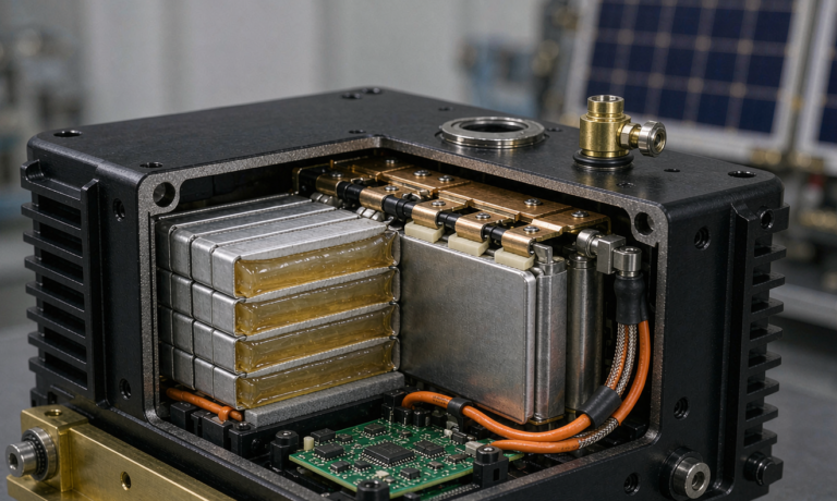
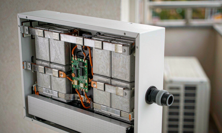
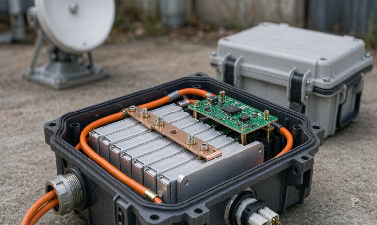
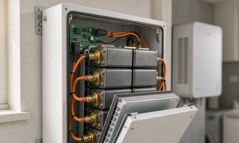
- IP-rated or ventilated? In a dry interior closet, a ventilated steel enclosure with filtered louvers beats a sealed IP65 box, because sealed boxes condense internally during rapid temperature swings. If the pack must live in a damp or dust-exposed space, IP65 with desiccant and a condensation drain is the correct call. Either way, match the rating to the actual environment as IEC 60529 defines it.
- Torque and re-torque. Every busbar and lug gets a calibrated torque wrench at commissioning (typical M8 terminal: 20–25 N·m), a re-torque at 6 months, and annual thermal-camera inspection. I have caught two developing hot spots this way — a 14 mV drop across a lug that read “fine” on a multimeter.
- Dissimilar-metal discipline. Copper busbar to aluminum cell terminal requires a bimetallic transition plate or antioxidant compound; galvanic corrosion at this joint is a slow-motion outage that appears in year two or three, long after the installer has left.
- DC disconnect and fusing per NEC 706. A properly rated Class T fuse on the pack main plus a load-break-rated disconnect is both a code requirement and the fastest diagnostic isolation point when something goes wrong at −15 °C.
Commissioning Validation: Prove Reliability Before You Need It
I never accept a cabin system on “it powered on and charged.” A three-day commissioning validation protocol catches 90% of latent integration problems while the installer is still on site:
- Day 1 — load bank and inrush test. Run the actual well pump, kitchen circuit, and heating loads through full start-stop cycles while logging pack current, voltage, and BMS events. Verify peak demand stays within the pack’s peak rating with 25% margin.
- Day 2 — generator failover drill. Force the SoC-floor auto-start, time the generator’s ramp and handoff, and verify charge-profile behavior on the BMS log. Repeat with a simulated comms failure (disconnect the CAN terminator) to confirm the system fails safe — defaulting to a conservative charge rate rather than refusing all charge.
- Day 3 — cold-soak behavior (seasonal). If commissioning in winter, verify heater activation, charge-inhibit behavior, and morning available capacity against the derating model. If commissioning in summer, simulate by programming the BMS test mode or scheduling a November follow-up visit.
Document everything. The commissioning log becomes the baseline for the annual service comparison — capacity, internal resistance, cell-voltage spread, and BMS event history — and that trend line is the only honest predictor of remaining system life.
A Twelve-Year Ownership Model
For a full-time 15 kWh cabin system, my planning model looks like this: year 0 commissioning and validation; annual service visit each September (torque check, thermal scan, capacity verification, firmware review — 2–3 hours); month-12 and month-24 recalibration of the SoC estimator; cell replacement is not expected before year 10–12 if the pack stays in its thermal comfort band and float exposure is limited. Budget-wise, owners should plan $150–250 per year in consumables (filters, desiccant, terminal treatment, one fuse spare) plus one inverter-firmware-and-config review per year. Against a $9,000–13,000 system capital cost, that is an honest reliability price of roughly 2% of capital annually — cheap insurance for a property where the alternative is a frozen plumbing stack.
Frequently Asked Questions
How long will a lithium battery last in an off-grid cabin?
A quality LFP pack cycled at 60–80% daily DOD in a temperature-managed enclosure typically delivers 3,500–5,000 cycles to 80% capacity — about 10–14 years in a full-time cabin application. The same pack left floating at 100% SoC in a hot closet will reach its end-of-life floor in 6–8 years. Temperature control and float discipline matter more than brand selection.
What size battery do I need for a cabin in winter?
Size for the worst design day, not the average: daily load in kWh divided by your realistic winter usable fraction. For a cabin with 4 kWh/day of winter load, that means 4 ÷ 0.75 (cold derating) ÷ 0.8 (usable window) ≈ 6.7 kWh of nameplate — I would specify 10 kWh to keep daily DOD under 50% and preserve cycle life, paired with either 1.5–2 kW of winter solar or the generator-hybrid dispatch described above.
Do lithium batteries work in freezing temperatures?
They discharge safely down to −20 °C (with reduced capacity and power), but charging below 0 °C causes lithium plating on the anode — permanent capacity loss and a genuine safety hazard. Any cold-climate cabin pack must either self-heat before accepting charge or have its BMS enforce a charge inhibit with heater coordination. This behavior is validated under IEC 62133-2 and IEC 62619 test regimes; demand the test evidence.
Should I add a generator to my cabin battery system?
Yes, if the cabin is used full-time or through winter. A two-wire-start generator integrated through the inverter’s generator input turns your worst-case reliability scenario (a week of polar-vortex overcast) from an outage into a 2-hour weekly fuel stop. For seasonal cabins with light loads, a well-sized solar-plus-storage system without a generator is often adequate.
How often should a cabin battery system be serviced?
Annually at minimum: terminal re-torque and thermal scan, capacity verification against the commissioning baseline, BMS event-log review, ventilation and desiccant check, and firmware updates applied in a controlled session. Systems with generator integration or high winter cycling benefit from a second mid-winter remote check of the SoC trend and heater operation.
What is the most common cause of cabin power outages?
In my monitored fleet it is BMS protection trips — overwhelmingly low-temperature charge lockouts and motor-inrush overcurrent events — followed by inverter configuration faults. Only a small fraction of downtime is actual cell degradation. Both leading causes are preventable at design time with heated enclosures, inrush-verified sizing, and a commissioning validation protocol.