Semi-Solid State Battery Thermal Runaway Protection Methods
Pack designers usually call me when an edge case keeps them awake at night. The one that always comes back is thermal runaway: the moment an internal short or overheat triggers a self-accelerating reaction that turns stored energy into heat faster than the system can reject it. In a conventional lithium-ion cell, the liquid electrolyte acts as a fuel vector. In a semi-solid state battery, the electrolyte is partially immobilized in a composite matrix, which changes the failure timeline but does not remove the risk. That is why our semi-solid state battery thermal runaway protection strategy is built from the cell chemistry up through the module and pack architecture. This article explains the methods I use at Horizon Power to keep semi-solid cells safe in the field.
The industry has moved past the idea that any single chemistry is inherently safe. Field data shows most serious pack fires start in modules assembled without propagation resistance in mind. My approach is layered: make the cell as tolerant as possible, slow propagation if it does fail, detect the event early, and validate every layer with abuse testing. Each layer buys time, and time is what turns a catastrophic failure into a contained one.
What Thermal Runaway Means in a Semi-Solid State Cell
Semi-solid state batteries sit between conventional lithium-ion and solid-state designs. They use a high-loading cathode, often NMC or lithium iron phosphate, paired with a gel-like or slurry electrolyte that contains less free liquid than a standard pouch cell. The lower liquid fraction means less volatile material to propagate a failure, but it also means the heat path is different. During an internal short, the cell heats locally. When the temperature crosses the separator shrinkage point, typically around 130 degrees Celsius for polyethylene separators, the electrodes can come into direct contact and create a sustained reaction.
Understanding the trigger is the first layer of protection. Internal shorts can come from separator puncture, lithium plating at the anode, contamination introduced during stacking, or mechanical crush. In a semi-solid cell, the electrolyte is less mobile, so the short tends to be more localized at first. Heat spreads by conduction through the current collector foils and the compressed cell stack. The key insight is that the cell will eventually reach this point under severe abuse; the goal is to delay it and prevent adjacent cells from following.
In my lab, we track three signals: surface temperature rise rate, vent gas pressure, and voltage collapse rate. A healthy cell under abuse might reach 70 degrees Celsius and stabilize. A cell heading into runaway shows a temperature rise above 1 degree Celsius per second, gas venting above a few hundred millibars, and a voltage drop to near zero within seconds. The semi-solid format gives us more time to act than a liquid cell, but only if protection layers are already in place. That extra time is measured in tens of seconds, so detection latency matters.
Cell-Level Protection: Electrolyte, Separator, and Additives
The first layer of protection is the chemistry itself. At Horizon Power, we specify flame-retardant additives in the electrolyte blend, typically phosphate esters at 5 to 15 percent by weight. These additives raise the self-extinguishing threshold and reduce peak heat release if a cell is breached. We also prefer ceramic-coated separators. The ceramic layer adds mechanical stability above the polymer melting point, which delays internal short growth by seconds to minutes depending on the severity.
Additives work in two ways. Some vaporize and interrupt the radical chain reactions that sustain electrolyte combustion. Others raise the flash point of the bulk electrolyte. We validate these choices with cone calorimetry on individual cells. A well-formulated semi-solid cell can cut peak heat release rate by 30 to 50 percent compared with a conventional liquid-electrolyte pouch. The separator also gets special attention: a 3 to 5 micrometer ceramic coating on a 9 micrometer polyethylene base gives a shutdown temperature near 135 degrees Celsius while maintaining pore structure up to 200 degrees Celsius.
Cell geometry matters. A pouch cell with a high aspect ratio and thin electrodes spreads heat over a larger surface, which helps rejection. A thick cylindrical format traps heat in the center and can accelerate local breakdown. For drone and small industrial packs, we lean toward pouch formats with electrode thickness that keeps the center temperature within 5 degrees Celsius of the surface under a 1 C discharge. We also set the upper voltage cut carefully. Pushing a semi-solid cell to 4.35 V instead of 4.20 V can deliver 8 to 10 percent more capacity, but it also increases the lithium plating risk that can seed an internal short. Our standard design window for NMC-based semi-solid cells is 3.0 V to 4.20 V, with a recommendation to stay below 4.10 V above 40 degrees Celsius.
Module-Level Protection: Barriers, Venting, and Cell Spacing
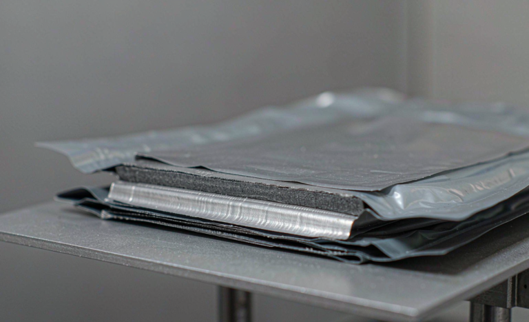
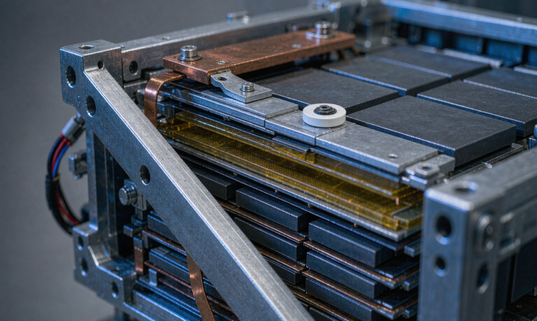
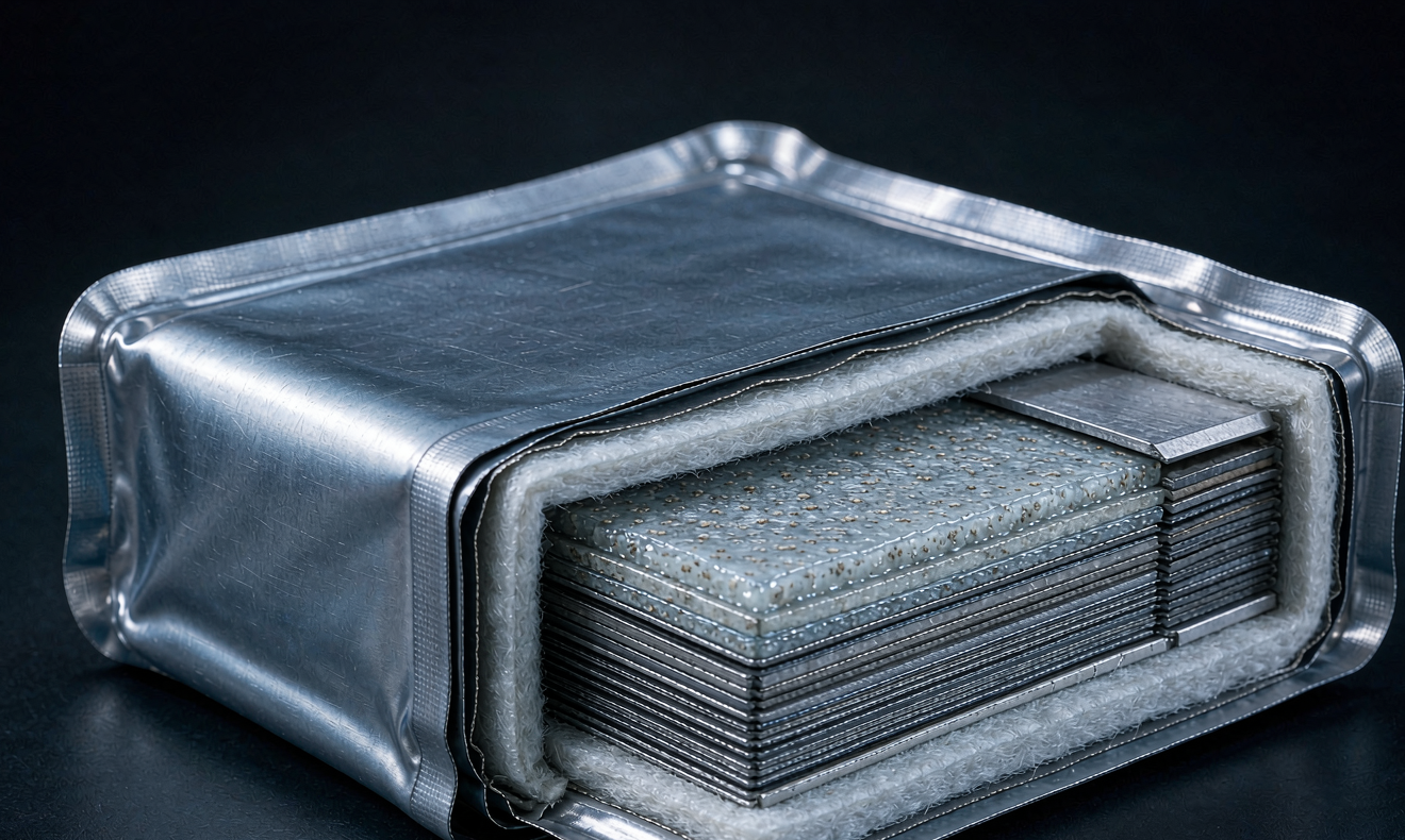
Even the best cell can fail if its neighbor heats it. Module-level protection starts with physical separation. We design our modules so each pouch cell has an interstitial barrier made from mica sheet, aerogel, or ceramic-fiber composite between adjacent cell faces. The goal is to keep a single-cell event from propagating to the next cell for at least 300 seconds, which is the window we target for first responders or autonomous shutdown to act. In testing, a 1.5 millimeter mica barrier can delay side-to-side propagation by over 400 seconds in a 5 Ah pouch test article.
The barrier design has to balance thermal resistance with weight and volume. Aerogel sheets insulate well for their mass but are fragile and need a compression frame. Mica is heavier but survives module assembly and vibration. Ceramic-fiber composites are our usual choice for drone packs where every gram matters but propagation must still be prevented. We also leave an air gap of 2 to 4 millimeters between the cell face and the barrier, which lets the failed cell vent into a controlled plenum rather than pressurizing the next cell.
Venting is the second line. Semi-solid cells still vent gas during thermal failure, though usually less violently than liquid electrolyte cells. We route vent paths away from adjacent cells and toward the module perimeter. The vent manifold must be sized so pressure does not back up into the failed cell and rupture the pouch seal. We use burst disks or spring-loaded relief valves rated at 150 to 300 millibars. Finally, we avoid tight compression around the cell edges. Semi-solid electrolytes need some stack pressure for interface stability, but excessive side-wall pressure can distort the pouch and create edge shorts. Our module frames apply pressure along the stack axis, not the free edges.
System-Level Protection: Detection and Response
The fastest protection is the one that turns off the current before the temperature climbs. Every pack we ship uses a battery management system with redundant temperature sensing. We place at least one thermistor per cell and additional sensors on the bus bars and power terminals. The firmware watches for three trip conditions: any cell above 60 degrees Celsius under charge, a temperature rise rate above 0.5 degrees Celsius per second, or a cell-to-cell delta above 15 degrees Celsius. Any one of these opens the main contactor and logs the event.
The contactor and fuse have to be matched to the short-circuit current. We specify fuses with a melting time below one millisecond at the prospective short-circuit current of the pack. In practice, that means a fuse rated at roughly 1.5 to 2 times the maximum continuous current. The battery management system controls the contactor; the fuse is the backup. We also add a manual service disconnect on the pack exterior with a clear label. No detection scheme matters if the people on site cannot isolate the system.
We also integrate gas detection in larger modules. Vent gas from a failing lithium cell contains hydrogen, carbon monoxide, and light hydrocarbons. A small electrochemical sensor in the pack enclosure can detect the early signature before surface temperature rises enough to trigger the thermistors. In one of our industrial prototypes, the gas sensor tripped 18 seconds before the temperature-based alarm during a nail-penetration test. That gap is enough to isolate the module. We pair detection with a failsafe contactor and a fuse rated for the pack short-circuit current. The contactor handles normal shutdown, the fuse handles the event where the contactor welds.
Abuse and Validation Testing
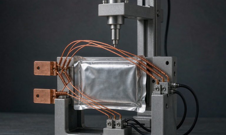
No protection claim matters without a test report. We run our semi-solid modules through a standard abuse suite: external short, overcharge to 130 percent state of charge, forced over-discharge, crush to 85 percent of original thickness, and nail penetration perpendicular to the electrode stack. The pass criterion is not that the cell survives, which is unrealistic for severe abuse, but that the failure stays within one cell and does not propagate. We record the data with a 10 Hz thermal camera and pressure transducer.
Test repeatability is critical. A single good result can be luck. We run propagation tests on at least three module samples and require no propagation in two of three to release the design. The one allowed propagation event has to stay within the module and not breach the pack enclosure. We also test at the worst-case state of charge, which is usually 100 percent for NMC cells and 80 to 100 percent for lithium iron phosphate.
Transport testing follows UN38.3 and the pack-level tests referenced by UN ECE R100 for traction batteries. For stationary systems, we use UL 9540A on module and pack samples when the customer requests it. The most useful test for our engineering team is the single-cell oven test at 150 degrees Celsius, which shows how the cell behaves when the separator is fully compromised. We want to see a controlled vent, not a jet fire, and we want the neighboring cells to stay below 80 degrees Celsius for the duration of the propagation test.
What is semi-solid state battery thermal runaway protection?
It is the combination of cell chemistry, physical barriers, venting, and electronic controls that prevents a single cell failure from turning into a pack-wide fire. In a semi-solid state battery, the protection system is tuned to the slower failure kinetics while still reacting in seconds.
How does a semi-solid state battery reduce thermal runaway risk?
The immobilized electrolyte holds less free liquid than a conventional cell, so there is less flammable vapor to feed a fire. The separator and additives also raise the temperature threshold for propagation. The risk is reduced, not eliminated, so module and pack protection are still required.
What materials stop thermal runaway propagation between cells?
Mica sheets, aerogel blankets, and ceramic-fiber composites are common inter-cell barriers. These materials resist the high heat flux from a failed cell and give the battery management system time to isolate the fault before it spreads.
How fast can a battery management system detect a runaway event?
With gas sensing, detection can occur 10 to 30 seconds before surface temperature alarms trigger. With temperature-only sensing, a well-placed thermistor can catch a 0.5 degree Celsius per second rise rate within 10 to 20 seconds. The contactor must open faster than the cell can heat its neighbors.
Which tests prove semi-solid state battery thermal runaway protection?
The standard suite includes nail penetration, overcharge, external short, crush, and oven exposure. For transport, UN38.3 applies. For larger systems, UL 9540A and UN ECE R100 propagation tests show whether a single-cell failure stays contained.
Further Reading
References