Semi-Solid Electrode Loading and Areal Capacity Guide
In twenty years of building cells I have watched more designs fail on the electrode coating bench than anywhere else. The chemistry can be flawless and the formation schedule perfect, but if the areal capacity is set wrong the cell will either fall short on energy or cannot be charged at the rate the application demands. Semi-solid electrode loading is the number that ties those two goals together, and it is the one I interrogate first when a customer sends a new specification. In this guide I explain what loading and areal capacity actually mean, how I measure them, the trade-offs I see in practice, and how to choose a target that survives real cycling rather than just a datasheet.
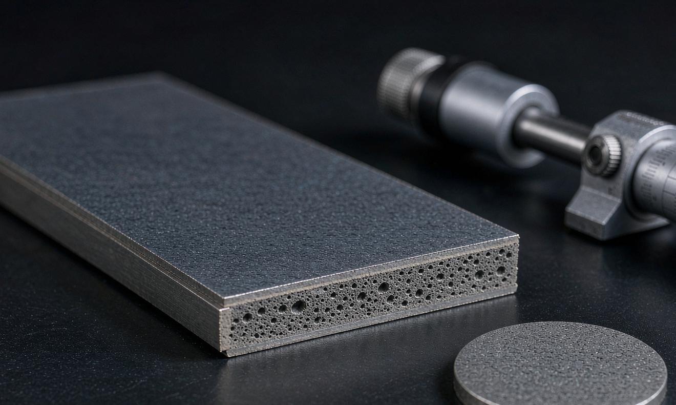
What Areal Capacity and Loading Actually Measure
Mass loading is the mass of active material coated per unit area of current collector, usually expressed in milligrams per square centimetre. Areal capacity is the charge that coating can deliver per unit area, written as milliamp-hours per square centimetre. The two are linked by the specific capacity of the active material: multiply loading by usable specific capacity and you get areal capacity. I always state both, because two electrodes with the same loading can deliver very different capacity depending on the material and how much of it is electrochemically accessible.
For a semi-solid system the distinction matters more than in a conventional liquid cell. The gel or quasi-solid electrolyte has to percolate through a thicker, denser electrode, so the simple loading number does not tell the whole story. I have seen a 4 mAh per square centimetre electrode behave like a 3 mAh one simply because the electrolyte could not wet the deepest pores. That is why I treat areal capacity as a measured outcome, not a number copied from a coating recipe.
How I Measure Loading on the Bench
My routine starts with mass. I punch discs of a fixed diameter from coated foil, weigh them on a calibrated microbalance, and strip the coating from a matched set to determine the bare foil mass. The difference, divided by the disc area, gives mass loading. I take at least ten samples across the web width and along the coating direction, because a single point hides the cross-web gradient that causes so much trouble later. A spread of more than a few percent tells me the coater needs attention before I commit to a full build.
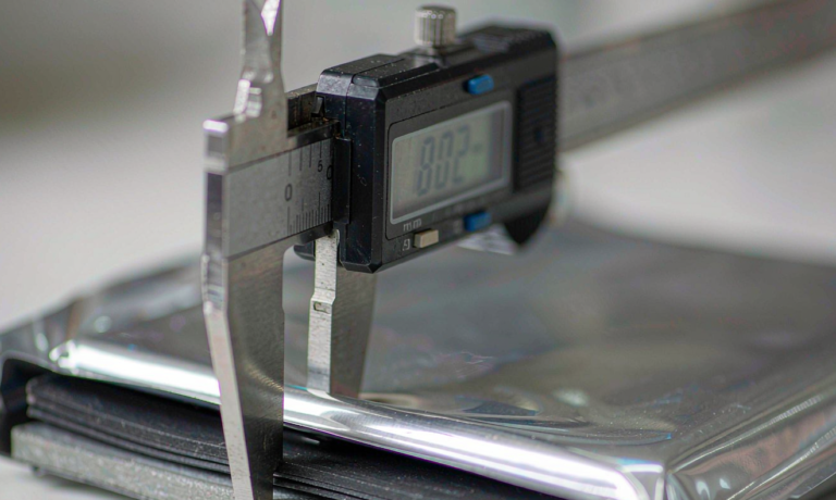
To cross-check, I measure coating thickness with a contact profilometer and calculate the porosity from the bulk and geometric densities. Thickness alone is misleading, since two coatings of the same thickness at different calendering pressures hold very different amounts of active material. I also confirm areal capacity electrochemically by building a small coin or pouch cell and dividing the delivered charge by the electrode area. When the gravimetric calculation and the electrochemical result disagree by more than about five percent, I assume the wetting is incomplete and go looking for the cause.
The Loading versus Rate Trade-off
Raising semi-solid electrode loading is the most direct way to increase cell energy density, because it reduces the fraction of inactive foil, separator, and packaging per unit of stored charge. That is why every program eventually pushes loading upward. The penalty is transport. A thicker electrode lengthens the path for lithium ions through the electrolyte-filled pores and for electrons through the conductive network, so polarization rises and the cell loses voltage under load.
In my own designs I treat roughly 2 to 4 mAh per square centimetre as a workable window for a quasi-solid electrode at moderate rate, and I go higher only when the duty cycle is gentle. Above that range the capacity gained at a slow discharge is often given back at a 1C or 2C rate, and the extra heat accelerates aging. I have tested stacks where doubling the loading lifted low-rate capacity by a third but cut usable power in half. For an energy-focused pack the trade can be worthwhile; for anything that sees fast charge or high current it is usually a mistake.
How Semi-Solid Electrolyte Changes the Calculation
A quasi-solid electrode is not simply a liquid cell with a stiffer separator. Part of the electrolyte phase is immobilized in a gel, and that changes both ionic conductivity and wetting kinetics. During calendering, the electrode pores can close enough that the gel precursor cannot penetrate to the current collector, leaving isolated active material that contributes mass but no capacity. This is the failure mode I watch for when loading climbs.
I address it in three ways. First, I keep the electrode porosity high enough, typically above roughly 30 percent, to leave a continuous path for the electrolyte. Second, I control the gel filling step with a vacuum soak and a dwell time long enough for the viscous precursor to reach the deepest pores. Third, I verify with a cross-section and an impedance spectrum rather than assuming fill is complete. A semi-solid electrode loading target is only meaningful if the electrolyte can actually reach every part of the coating, and I have learned to prove that before scaling.
Loading, Porosity, and Calendering Control
Calendering is where a coating becomes an electrode, and it is the lever that sets porosity for a given loading. Press too lightly and the particles touch poorly, so electronic resistance climbs and the coating may shed material. Press too hard and the pores collapse, ionic transport stalls, and the gel cannot fill the structure. Somewhere between lies a density window that balances contact and transport, and it shifts with the particle morphology of the active material.
I map that window for every new formulation rather than inheriting a setting from a previous program. I calender a small matrix of coupons at increasing pressure, measure thickness and porosity on each, then build cells and compare rate capability and impedance. The resulting curve tells me the maximum density that still preserves access to the pores. Once that is fixed, I hold calendering pressure tightly in production, because a small drift here shows up as a scatter in areal capacity that no amount of formation cycling can repair.
Choosing a Target and Specifying It Clearly
When a customer asks what loading they should specify, I start from the duty cycle, not from a competitor datasheet. A stationary buffer battery that discharges over hours can carry a high areal capacity and accept the rate penalty. A high-power module needs a thinner, more porous electrode with lower loading and better kinetics. I then work backward to a loading range, a porosity band, and an acceptable coating uniformity, and I write all three into the specification.
A useful spec also names the test method. I state the punch diameter, the number of sample points, the calendering pressure, and whether areal capacity is calculated gravimetrically or measured electrochemically at a defined C-rate. Without that detail two suppliers can report the same number while delivering very different electrodes. At Horizon Power I share the measured distribution, not just an average, because the tails of that distribution determine yield and long-term consistency. If you are evaluating a semi-solid cell and the loading figure arrives without a method, that is the first question I would ask.
Frequently Asked Questions
What is a typical areal capacity for a semi-solid electrode?
Most quasi-solid designs I work with sit between roughly 2 and 4 mAh per square centimetre at moderate rate. Energy-focused cells may go higher, but they sacrifice power. The right value depends on the material, the porosity after calendering, and how completely the gel electrolyte fills the electrode.
Why does higher loading reduce rate capability?
A thicker coating lengthens the ion path through the pores and the electron path through the conductive network. Polarization rises, so the cell gives less voltage and capacity at high current. The extra energy at slow discharge can be largely lost at 1C or 2C if the electrode was not designed for it.
How is mass loading measured in practice?
I punch discs of known area, weigh them, and compare against stripped bare foil to isolate the coating mass. I sample many points across the web to catch gradients, then cross-check with thickness and porosity measurements and an electrochemical capacity check on a small cell.
What role does porosity play in semi-solid electrodes?
Porosity keeps a continuous channel for the gel electrolyte to reach active material. If calendering closes those pores, parts of a high-loading coating become electrically isolated and add mass without capacity. I usually keep porosity above about 30 percent and verify fill with cross-sections and impedance.
Can areal capacity be estimated from thickness alone?
No. Two coatings of identical thickness can hold different amounts of active material depending on density and porosity. Thickness is useful as a process check, but areal capacity should be confirmed by mass measurement and, ideally, by the charge a test cell actually delivers.
What standards cover electrode safety and transport?
Loading itself is a design parameter, not a regulated limit, but the resulting cell still has to meet safety and shipping rules. Semi-solid packs are commonly qualified against IEC 62133 and IEC 62619 for safety, and UN38.3 for transport. I recommend confirming the specific standard set with the test lab for your market.
Further Reading
References