Semi-Solid State Battery Module Interconnect and Fusing
I have spent the better part of a decade on the production floor and in the test lab at Horizon Power, and if there is one step where a promising semi-solid cell turns into a disappointing pack, it is the module interconnect. The chemistry gets the headlines, but the busbars, the welds, and the fuses are what decide whether a semi-solid state battery module is safe, serviceable, and profitable to build. In this article I want to walk through how we engineer interconnects and overcurrent protection for semi-solid cells, and where the rules differ from the lithium-ion packs most engineers already know.
Why Module Interconnect Design Changes for Semi-Solid Electrolytes
A semi-solid state cell is not simply a lithium-ion cell with a thicker electrolyte. The electrode is a composite with higher active-material loading and, in many layouts, a softer, more compressible structure than a conventional wound cell. That single physical fact ripples through the entire interconnect strategy.
First, the energy density is higher for a given footprint, so a module packs more ampere-hours behind the same busbar. Peak discharge current scales with capacity, and so does the fault current if a cell goes internal short. The interconnect that was comfortably oversized on a 50 Ah lithium-ion module may sit right at its limit on a 120 Ah semi-solid module.
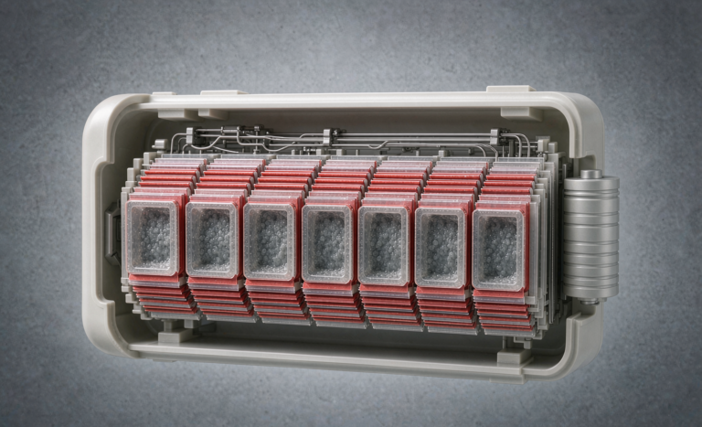
Second, semi-solid electrodes often like a small stack pressure to keep interfacial contact. That pressure is applied through the end plates and, indirectly, through the cell terminals. If the interconnect introduces a mechanical fulcrum or an uneven torque path, you get micro-movement at the terminal, fretting, and eventually a high-resistance joint. We design terminals and busbars as part of the mechanical stack, not as an afterthought.
Third, the internal resistance of a fresh semi-solid cell can be lower than an equivalent lithium-ion cell at the same state of charge, which means the prospective short-circuit current is higher and the fuse must clear faster. These three shifts are why we re-derive the interconnect from scratch for every new semi-solid format rather than copying a lithium-ion drawing.
Busbar Sizing: Material, Cross-Section, and Temperature Rise
Choosing between nickel, copper, and nickel-clad copper
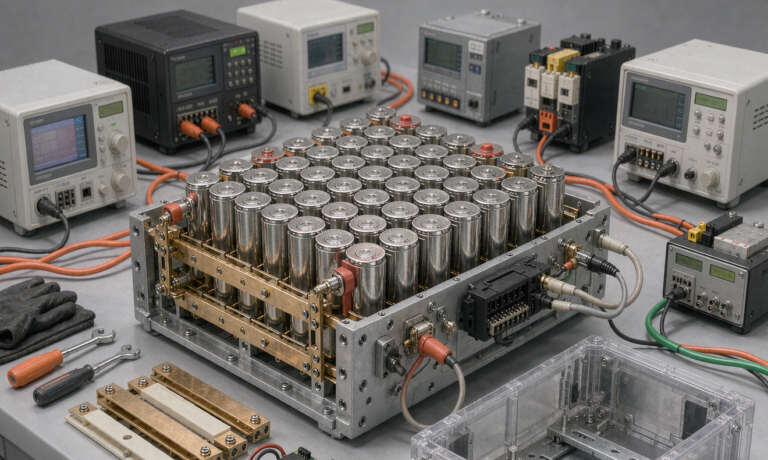
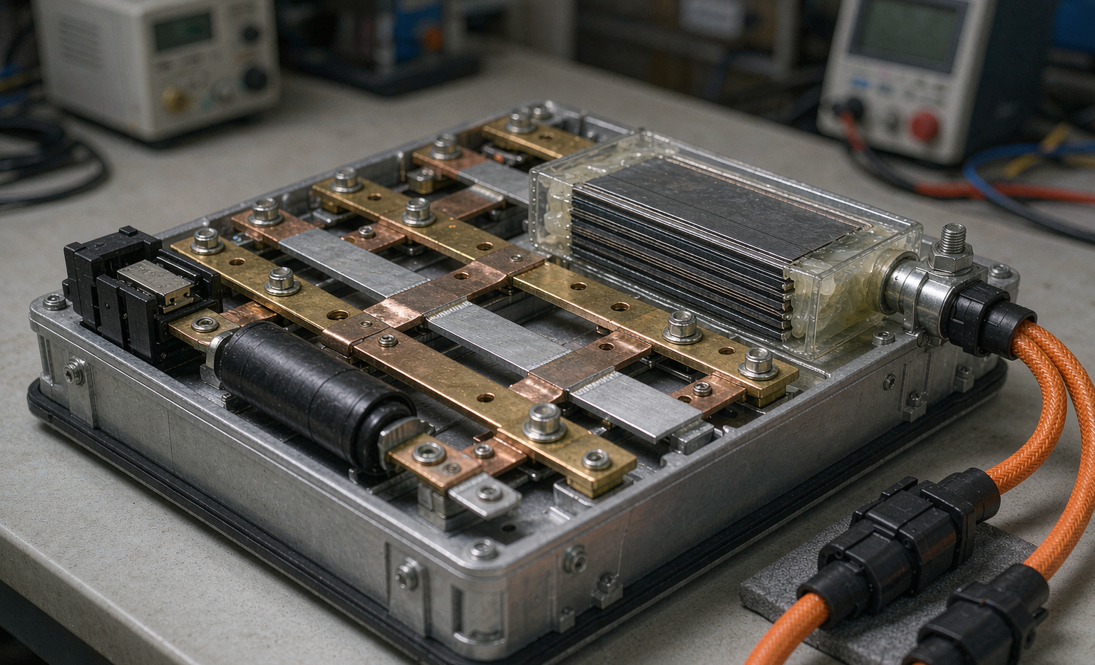
The classic trade is pure nickel versus copper. Nickel is easy to resistance-weld, resists corrosion, and matches the cell tab chemistry, but its conductivity is roughly a quarter of copper. Copper carries far more current per gram, but it is harder to weld directly to aluminum or nickel tabs and it creeps under sustained clamp load. On most semi-solid modules we land on nickel-clad copper: a copper core for conduction wrapped in a thin nickel skin for weldability and corrosion resistance. The skin is thin enough that the bulk resistance is dominated by copper, and the joint stays clean.
Working the I-squared-t and temperature-rise math
Sizing starts with the continuous current and a temperature-rise budget. For a module we typically allow a 30 to 40 degrees Celsius rise at the busbar surface under the worst expected continuous load, measured in still air at 25 degrees Celsius. The cross-sectional area follows from the allowed current density, which we keep in the 3 to 6 amperes per square millimeter range for nickel-clad copper depending on the cooling path.
The more demanding number is the short-circuit case. A busbar must survive the let-through energy of a fault long enough for the fuse to clear, and that is an I-squared-t problem, not a steady-state one. We model the prospective fault current from the cell impedance, then confirm the busbar melt integral is safely above the fuse clearing integral so the fuse, not the busbar, is the sacrificial element. If the busbar would melt before the fuse opens, the design has failed its most basic test.
Current Sharing Across Parallel Cells
Why batch impedance spread matters more here
When cells are paralleled in a module, the cell with the lowest impedance quietly carries the most current. In lithium-ion this is usually managed with tight sorting. Semi-solid batches can show a wider impedance spread early in a production ramp, and that spread is amplified by the higher peak currents we just discussed. A 10 percent impedance mismatch that is harmless at 1 C can become a 20 percent current imbalance at 5 C, and the hot cell ages faster, which widens the mismatch further.
Sense lines and Kelvin connections
We address this with per-cell voltage sensing and, on high-rate modules, Kelvin-style four-wire connections at the terminal so the BMS sees true cell voltage rather than the voltage dropped across the interconnect. Active balancing helps, but the cheaper and more reliable fix is tight incoming sorting plus a busbar layout that gives every parallel group an equal path length and equal joint count. Equal path length is not cosmetic; a few milliohms of extra busbar on one leg is enough to skew sharing.
Fuse Placement: Cell, Module, and Pack Levels
The fusible link between parallel groups
A fuse is only useful if it sits where the fault current actually flows through it. On a module we think in three layers. At the pack level, a main fuse or contactor protects the whole assembly. At the module level, we protect each parallel group with a fusible link sized to clear a single-cell internal short without taking down the neighboring healthy cells. Cell-level fuses exist in theory but add too much resistance and cost for most semi-solid modules, so the practical compromise is a module-level fusible link at every parallel branch.
Pyro-fuses for high-voltage isolation
Above roughly 60 volts we add a pyrotechnic disconnect, the so-called pyro-fuse, that the BMS can fire to physically sever the high-voltage bus in milliseconds during a severe fault or crash signal. The pyro-fuse is not a slow overcurrent device; it is an isolation switch with a guaranteed break. We locate it so that firing it leaves no energized exposed conductor, and we test the firing circuit independently of the main control board so a board failure cannot block the disconnect.
Detecting a Failing Cell Before It Blows
Delta-V and temperature as early warnings
A fuse is the last line of defense, not the first. Long before a cell reaches the current that blows its link, it usually signals trouble through a widening delta-V against its neighbors or a localized temperature rise the passive balancing cannot explain. We log per-cell voltage and temperature at a cadence fast enough to catch a developing short, and the BMS flags a cell for service when its deviation crosses a threshold we set from batch data rather than a fixed guess.
I remember a field return where a single semi-solid cell ran 40 millivolts below its group under load. Nothing blew, because the sensing caught it in the first cycle and the module was pulled before the weak cell could drag the busbar into a thermal event. That is the whole point: the interconnect and fuse are engineered so a single bad cell is a maintenance ticket, not a fire report.
Welding, Laser Joints, and Production Inspection
Ultrasonic versus resistance welding
The busbar-to-tab joint is the joint that fails in the field, so we obsess over it. For nickel and nickel-clad tabs we favor resistance welding with a tightly controlled weld schedule, and for copper-heavy joints we move to laser welding with pre- and post-weld cleaning. Ultrasonic welding earns its place when we need to join dissimilar metals or very thin foils without heating the cell, but it demands careful horn design to avoid cracking the brittle semi-solid electrode near the tab.
X-ray and torque verification
Every weld class is qualified on a coupon, then sampled by X-ray on production parts to confirm nugget size and absence of voids. Mechanical links get a torque verification step, because a bolt that was right on the fixture can loosen after a few thermal cycles. We treat the interconnect as a safety-critical assembly, which means traceability from the cell lot through the weld schedule to the finished module serial number.
Frequently Asked Questions
What is the difference between a busbar and a fuse in a battery module?
A busbar is the conductive path that carries normal operating current between cells, while a fuse is a deliberately weak link that melts to break fault current. The busbar is sized for continuous duty and low loss; the fuse is sized to fail first and protect everything around it.
Why does semi-solid state need different interconnect design than lithium-ion?
Semi-solid cells often pack more capacity per footprint, run at lower internal resistance, and need stack pressure, so fault currents are higher and mechanical joints are more sensitive to movement. Those shifts change busbar sizing, fuse clearing time, and weld strategy.
How do you size a fuse for a semi-solid state battery module?
We start from the prospective short-circuit current derived from cell impedance, then choose a fuse whose clearing I-squared-t is below the busbar melt integral and above the normal operating let-through, so the fuse opens without nuisance trips and the busbar never melts.
Can a semi-solid state battery module use off-the-shelf fuses?
Often yes for the pack-level main fuse, but the module-level fusible links are usually custom-rated for the branch fault current and the tight space. Using a generic fuse without checking the clearing integral against the busbar is a common and dangerous shortcut.
What welding method is best for semi-solid state busbars?
It depends on the tab metal. Nickel and nickel-clad tabs suit resistance or laser welding with controlled schedules; copper-heavy joints favor laser with cleaning; ultrasonic helps for dissimilar or thin foils but needs careful horn design to protect the electrode.
How does Horizon Power validate module interconnect reliability?
We qualify each weld on coupons, sample production joints by X-ray, verify torque on mechanical links, and run module-level short, overcurrent, and thermal-cycle tests, then trace every unit from cell lot to serial number for field accountability.
Getting the interconnect and fusing right is what turns a great semi-solid cell into a pack a customer can trust. If you are specifying a semi-solid state battery module for a high-rate or high-voltage application, talk to our engineering team about a custom battery solution built around your real duty cycle rather than a catalog drawing.
Further Reading
References