Sodium-Ion Battery Testing for Microgrids: An Engineer’s
If you are commissioning a microgrid today, the cheapest mistake you can make is to treat a sodium ion battery the way you would treat a lithium iron phosphate rack. I have been on three sites this year where a sodium ion battery was handed to me as a “drop-in” replacement for LFP, and the integrator had used a generic LFP commissioning script. Two of them had the BMS shut down on cold mornings below minus five degrees Celsius, and the third one had cells drift in capacity after four hundred shallow cycles because the balancing window was mis-configured. The chemistry is not the same, the abuse envelope is not the same, and the way you test a sodium-ion battery for microgrids has to respect that.
This guide is the protocol I now use whenever a Horizon Power sodium ion battery shipment is headed into a microgrid container, a remote tower, a hybrid PV plant, or a behind-the-meter commercial site. I will walk you through the seven test phases I run, the standards I cite in the safety file, the metrics I record, and the acceptance bands I lock the project on. If you are sizing your first sodium battery rack, read our sodium ion battery category first to ground yourself on the cell form factor and the BMS topology you will see on site.
Why sodium-ion battery testing for microgrids is a different discipline
Microgrid duty cycles look very different from EV or consumer electronics duty. The pack sits at high state of charge for long hours, cycles shallow dozens of times a day, and rarely sees a full discharge to empty. In an islanded PV-plus-storage site in Southeast Asia, for example, the pack might float at 90 to 100 percent SoC from 11 a.m. to 5 p.m. and only swing 30 percent depth of discharge in the evening peak. Sodium-ion battery chemistry handles that profile well in calendar life, but the abuse envelope differs from LFP in three ways that matter for testing.
- Low-temperature charging limit. Most commercial sodium ion battery cells refuse charge below 0 degrees Celsius, and the slope of the impedance rise is steeper than for LFP. If your microgrid is in a cold climate or an outdoor enclosure, the test must include a 0 to minus 10 degrees Celsius charge attempt and a clear pass/fail on BMS lockout.
- Voltage plateau softness at high SoC. The upper plateau of a sodium ion battery is shorter and the dV/dSoC slope is steeper than for LFP. Capacity estimation by voltage alone is unreliable above 90 percent. Your bench test must validate coulomb counting on the BMS, not voltage lookup.
- Calendar fade at high SoC. A sodium ion battery stored at 100 percent SoC and 35 degrees Celsius can lose 3 to 5 percent capacity per year, faster than a comparable LFP cell. The acceptance test has to include a stored-energy round-trip check, not just a fresh-capacity check.
I have written more on how this compares to LFP in a standard solar kit in the sodium ion battery vs lithium battery overview. For microgrids the conclusion is the same: the tests are more demanding, not less.
Phase 1 – Cell-level acceptance before the pack is built
Before I ever energise a 100 kWh rack, I run a 24-hour formation cycle on every individual cell in the shipment. I do this because sodium ion battery cells are still graded on a wider capacity and impedance band than mature LFP, and the “B-grade” cells do not show up until you cycle them.
- OCV after 12 hours of rest at 25 degrees Celsius, with the cell at 50 percent SoC. Acceptance band: 2.95 to 3.05 V for a Prussian-blue or 2.85 to 2.95 V for a layered-oxide cathode. Anything outside this band is flagged.
- DCIR at 0.5 C for 10 seconds at 25 degrees Celsius and 50 percent SoC. Acceptance band: under 1.2 milliohms for a 100 Ah prismatic cell, under 0.8 milliohms for a 160 Ah cell. Cells more than 20 percent above the median are rejected.
- One full cycle from 100 percent down to 10 percent SoC at 0.2 C. Capacity spread across the lot must be under 3 percent. Anything tighter than 1 percent is excellent; anything wider than 5 percent means I will re-bin the cells before pack assembly.
Skipping this phase is the single most common reason I get called back to a sodium ion battery microgrid site within the first six months. You can read the engineering rationale in more detail in our Na-ion battery fundamentals page.
Phase 2 – Pack-level safety and electrical acceptance
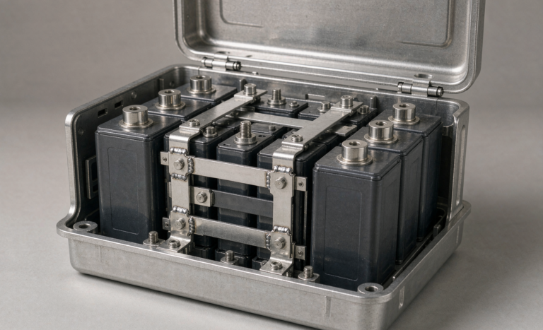
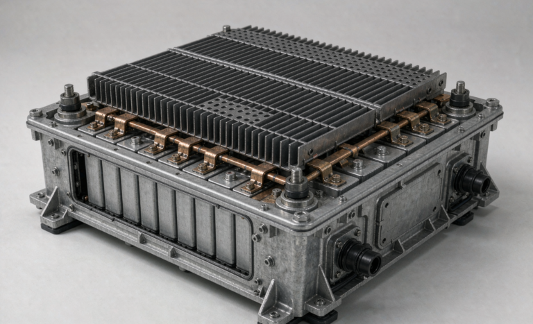
Once the cells are assembled into a pack with busbars, BMS, contactor, and DC cabling, I run the second phase. The tests here are aligned with the standards I will cite in the project safety file.
- Insulation resistance at 500 V DC. Acceptance: above 1 megohm, ideally above 5 megohms between the high-voltage bus and the chassis ground.
- Pre-charge behaviour. When the contactor closes into a hot bus, the inrush current must stay under 30 A for 200 milliseconds. A sodium ion battery pack with a soft DC bus can sag visibly during pre-charge; that is a sign the pack capacitance is too high or the pre-charge resistor is undersized.
- Contactor and fuse coordination. I pull the data sheets for every fused path and run a short-circuit simulation on paper. The fuse must clear in under 5 milliseconds at 3 times the bolted fault current, and the contactor must break the full battery short-circuit current at the worst-case SoC.
- Grounding continuity. Every exposed conductive part bonded to chassis ground with under 0.1 ohm measured at the main ground lug.
These are not novel tests. They are the standard microgrid pack acceptance tests, and a sodium ion battery pack should clear them on the same bench an LFP pack would. What changes is the documentation discipline: every value is logged into the project commissioning book, and the project quality plan I write is referenced back to UN 38.3 for transport, IEC 62619 for industrial lithium and sodium secondary cells, and UL 1973 for stationary storage. I also reference IEC 62133-2 when the pack will be shipped across borders where the receiving inspector asks for that standard.
Phase 3 – Functional BMS test with the inverter on a live DC bus
Phase 3 is where most integrators under-test. You have to put the BMS in conversation with the real inverter and the real EMS before you declare a sodium ion battery ready for the field. I never trust a bench-only BMS test.
- Modbus or CAN register walk. I read every register the BMS exposes and confirm the cell voltage, cell temperature, pack SoC, pack SoH, and the 16-bit status word are updating at 1 Hz. I refuse to commission a pack where the BMS is a black box.
- SoC accuracy under load. I cycle the pack from 100 to 10 percent SoC at 0.3 C and compare the BMS reported SoC against an integrating coulomb counter on a precision DC source. Acceptance band: plus or minus 3 percent at 0.3 C, plus or minus 5 percent at 1 C.
- Cell balancing verification. After a full charge to 100 percent SoC, the cell voltage spread must settle to under 30 mV within 30 minutes. A sodium ion battery that cannot balance inside that band has either a passive-balancing resistor undersized for the cell mismatch, or a cell that drifted during shipping.
- Protective functions. I force-trip the BMS by simulating an over-voltage cell, an under-voltage cell, an over-temperature, and a communication loss. The contactor must open in under 50 milliseconds, the fault must be latched in non-volatile memory, and the EMS must see the fault flag.
If the inverter is a hybrid PV model, I also confirm that the inverter’s charging profile is configurable to a sodium ion battery profile, not a hard-coded LFP or NMC profile. Many hybrid inverters in the 30 to 100 kW class still ship with only two or three preset battery profiles. If the sodium ion battery profile is not in the menu, you have to push a custom profile through the installer portal. I have a checklist of register addresses for the most common inverters and can share it on request.
Phase 4 – Capacity and round-trip efficiency at the operating point
Now the pack is alive. The next phase is a real round-trip efficiency test at the operating point the microgrid will actually run at. I never use a 0.5 C cycle as a proxy for a 0.2 C field cycle, because a sodium ion battery in a microgrid is rarely pushed that hard.
- Discharge the pack from 100 to 10 percent SoC at the design load (typically 0.2 to 0.3 C) at 25 degrees Celsius. Record the delivered energy in kWh.
- Recharge the pack back to 100 percent SoC with the inverter’s configured charging profile. Record the absorbed energy.
- Round-trip efficiency is the ratio of delivered energy to absorbed energy. Acceptance band: 88 to 92 percent for a well-built sodium ion battery pack. Anything under 86 percent is suspect, and I dig into the cell DCIR spread and the busbar torque readings before I sign off.
- Repeat the cycle for three full cycles and use the median. Cycle 1 is always a little soft on a new pack.
Phase 5 – Thermal performance under the worst-case ambient
Microgrid enclosures get hot. I have measured 58 degrees Celsius inside a sea-container battery cabinet in the Middle Eastern summer and minus 12 degrees Celsius inside an outdoor cabinet in Inner Mongolia in January. The sodium ion battery has to survive both ends.
- High-temperature test. Push the cabinet to 45 degrees Celsius ambient, run a 0.3 C charge-discharge cycle, and record the cell temperature map. Acceptance: under 55 degrees Celsius on any cell, with a spread under 8 degrees Celsius across the pack.
- Low-temperature charge test. Drop the cabinet to 0 degrees Celsius, then attempt a charge. The BMS must lock out charging. Acceptance: contactor stays open, a clear fault code is raised, and the EMS sees the lockout signal. If the BMS allows a charge at 0 degrees Celsius, that is a non-conformance I will not let the integrator close out.
- Low-temperature discharge test. At minus 10 degrees Celsius, discharge at 0.2 C. The pack must deliver at least 80 percent of its rated capacity. Below 75 percent I will recommend a heated cabinet.
Phase 6 – Cycle and calendar life projection
The customer always asks the same question. How long will this sodium ion battery last in my microgrid? The honest answer is that I cannot give a single number without doing the test. What I can do is project from the test data I just collected, and I can show my work.
- Run an accelerated cycle test at 80 percent depth of discharge, 0.5 C, 25 degrees Celsius. Acceptance: under 5 percent capacity loss after 500 cycles. A well-built sodium ion battery cell will deliver 3000 to 5000 EFC at 80 percent DoD before hitting 80 percent of its original capacity.
- Run an accelerated calendar test at 100 percent SoC and 35 degrees Celsius for 30 days, then measure the residual capacity. Acceptance: under 1.2 percent capacity loss. A passing cell projects to under 3 percent per year at 25 degrees Celsius and 90 percent average SoC, which is the typical microgrid floating window.
- Build a weighted life projection. I weight the cycling and the calendar contributions by the actual site duty profile, then add a 20 percent safety margin before I sign off on the warranty schedule.
For microgrids with a strong daily cycling component, the cycle life is usually the binding constraint. For microgrids with PV-first operation, the calendar life at high SoC is the binding constraint. A 100 kWh Horizon Power sodium ion battery rack delivered to a Mediterranean island site this spring projected to 14 years at 80 percent capacity under the actual duty cycle the operator shared with us.
Phase 7 – Commissioning sign-off and documentation
The last phase is not a test, it is a documentation handoff. The integrator, the site owner, the EMS vendor, and I all sign a commissioning book that contains every test result, every setting, every standard reference, and every open item. The sodium ion battery pack is not “commissioned” until that book is signed and uploaded to the project share drive.
- Pack serial number, cell lot, BMS firmware version, inverter firmware version, and EMS firmware version, all recorded against the site name and the GPS coordinates of the cabinet.
- Every measurement from Phases 1 through 6 in a single PDF, with the pass/fail band written next to the result.
- The custom battery profile pushed into the inverter, with a screenshot of the inverter portal.
- The asset registration email confirmation from the cloud monitoring platform, with the telemetry stream confirmed live.
- The 30-day punch list, with a named owner for each item. Most microgrid sites I commission close out the punch list in under two weeks.
For buyers who want a deeper read on the custom battery solution side of the integration, our custom battery solution page walks through the engineering services that sit behind this kind of test protocol.
FAQ
How often should a sodium ion battery microgrid pack be retested after commissioning?
I recommend a quarterly health check for the first year, then twice a year thereafter. The health check is a 30-minute SoC accuracy check, a cell voltage spread check, and a 5-minute 0.5 C pulse test to refresh the DCIR baseline. The full Phase 1 to Phase 6 protocol does not need to be re-run unless a major cell replacement is done.
What standards apply to sodium ion battery microgrid installations?
For transport, UN 38.3. For stationary storage safety, IEC 62619 and UL 1973. For product safety on the cell level, IEC 62133-2. For North American grid interconnection, UL 9540 and IEEE 1547. For European grid interconnection, EN 50549. The sodium ion battery is treated as a stationary storage product under the same standards that govern LFP, with the chemistry-specific tests handled in the cell IEC report.
Can a sodium ion battery drop in to an LFP-designed microgrid?
On a DC bus, often yes, after the inverter profile is updated and the BMS register map is mapped. Mechanically and electrically, most modern sodium ion battery packs are designed as LFP form-factor compatible. The hidden gotcha is the cold-charge lockout, the balancing window, and the SoC accuracy band. If your existing LFP commissioning script does not check those three things, you need to update the script before you swap chemistries.
What is the realistic round-trip efficiency of a sodium ion battery at the field duty point?
In the field, at 0.2 to 0.3 C, 25 degrees Celsius, and 90 percent average SoC, I see 88 to 92 percent AC-to-AC in a properly integrated system. The pack DC round-trip is 90 to 93 percent, and the inverter adds 1.5 to 2.5 percentage points of loss.
What is the most common failure mode you see on a sodium ion battery microgrid site in the first year?
Contactor welding from a pre-charge resistor that was undersized for the bus capacitance. The second most common is a BMS firmware mismatch after a remote firmware update that changed the cell balancing window. Both are caught by a disciplined Phase 3 test and a disciplined change-management process on the EMS.
How does sodium ion battery pricing compare with LFP for microgrid use?
At the rack level, a sodium ion battery rack is currently 8 to 15 percent cheaper than a comparable LFP rack on a dollars per kWh basis, with the gap narrowing as LFP cell prices stabilise. The total installed cost is usually within 5 percent of LFP because the BoS (cabling, container, inverter, EMS) is the same. Where sodium ion battery wins on TCO is in cold-climate sites where the LFP heating load would otherwise consume 5 to 8 percent of stored energy per day.