Sodium-Ion Battery Design for Microgrids
I have spent the last eleven years designing battery systems, and the projects that taught me the most were not the elegant ones. They were the rural microgrids where a cabinet had to survive a summer at 48 °C ambient, a winter at −25 °C, and a maintenance visit once every eighteen months. Sodium-ion changed what I can promise on those sites. But it also changed the design rules, and engineers who copy a lithium battery architecture straight across get bitten. This article is the design sequence I actually follow, in the order I follow it, with the numbers I hold myself to.
Design Starts With the Load Profile, Not the Cell
Every failed microgrid design I have reviewed started with someone choosing a cell. The correct starting point is eight hours of measured load data and the worst credible generation week. From that I extract four numbers: peak power, sustained power, daily energy throughput, and the longest no-generation interval. A village clinic microgrid I designed in 2023 showed a 14 kW peak but only 3.1 kW sustained draw and 61 kWh of daily throughput. Sizing to the peak would have doubled the cabinet. Sizing to sustained power with a 20-second peak allowance produced a 90 kWh, 25 kW system that has never hit a power limit. Discharge duration then sets the C-rate, and the C-rate governs almost every downstream decision: thermal load, busbar section, cell format, and how much margin the balancing circuit needs. Most microgrids land between 0.2C and 0.5C. That is a comfortable region for sodium-ion, and it is why the chemistry fits this application better than it fits a drone battery.
Choosing the Cell Format Before Anything Is Fixed
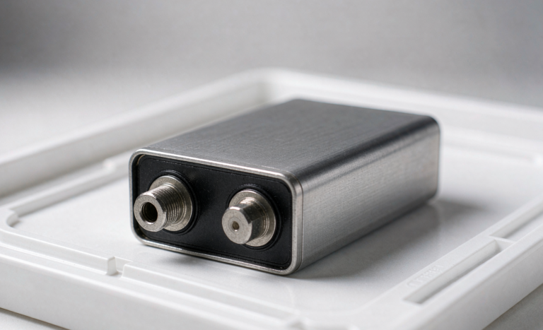
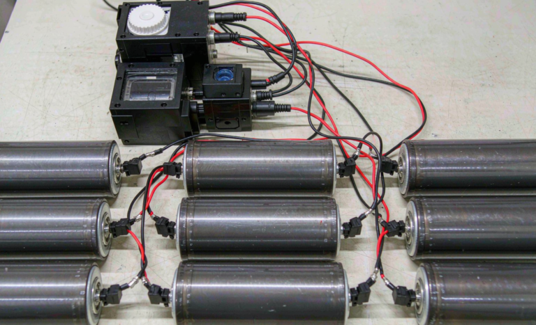
Sodium-ion arrives in cylindrical 26700/32140 cells and in prismatic hardcase formats. For microgrid cabinets I default to prismatic. The reason is thermal, not commercial: a prismatic cell presents two large flat faces to a cold plate or an air channel, so the internal temperature gradient at 0.5C stays inside 4–6 K, while a dense cylindrical pack of the same energy typically shows 8–12 K core-to-surface. Gradient drives cell-to-cell divergence, and divergence is what eventually strands capacity. Current sodium-ion cells deliver roughly 100–160 Wh/kg at cell level, against 150–180 Wh/kg for LFP and 250–300 Wh/kg for high-nickel lithium battery cells. On a fixed-footprint site that penalty is real, so I confirm the cabinet envelope before committing. What buys the penalty back is temperature range and cost trajectory. I also confirm the cell datasheet states a zero-volt storage tolerance, because it changes the entire logistics and commissioning plan.
Designing the Voltage Window Around a Sloping OCV Curve
This is the single biggest difference from lithium work. LFP has a flat plateau, so state of charge must be tracked by coulomb counting and periodically re-anchored. Sodium-ion has a strongly sloping open-circuit-voltage curve, typically from about 4.0 V down to 1.5–2.0 V per cell with a nominal near 3.0–3.2 V. That slope is a gift: voltage-based SoC estimation lands within 3–5 % without aggressive filtering, which matters enormously on a microgrid where the controller needs honest SoC to dispatch a generator. The design cost is that the DC bus swings much harder. A 96-series string that runs 288 V nominal can reach 384 V full and drop near 192 V deep, a range of roughly 2:1. Any converter selected must accept that window at full power, not just at derated power. I have seen two projects where the battery was correct and the power conversion stage clipped 15 % of usable energy purely because the voltage window was specified from nominal.
String and Parallel Architecture
I size the series count from the converter’s minimum operating voltage plus a 10 % margin, never from the nominal. Then I decide how many strings sit in parallel. Two strings is my minimum for any site with a service interval longer than six months, because it lets the system run at half power with one string isolated instead of going dark. Above four parallel strings I insist on per-string contactors and per-string current measurement; without them a single weak module quietly draws circulating current and nobody sees it until a capacity test fails. Circulating current between parallel sodium-ion strings is somewhat better behaved than lithium iron phosphate because the sloping curve makes voltage mismatch self-correcting, but a 25 mV static offset across a 5 mΩ path still moves 5 A. I specify strings from the same production lot, matched on 1 kHz AC internal resistance to within ±0.5 mΩ and on 0.5C capacity to within ±2 %.
Current Path Design: Busbars, Fusing, and Joints
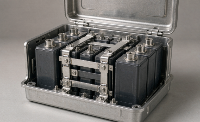
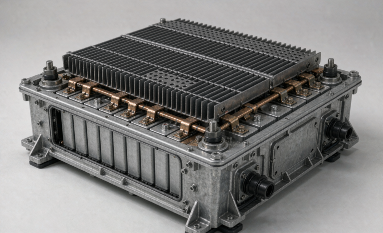
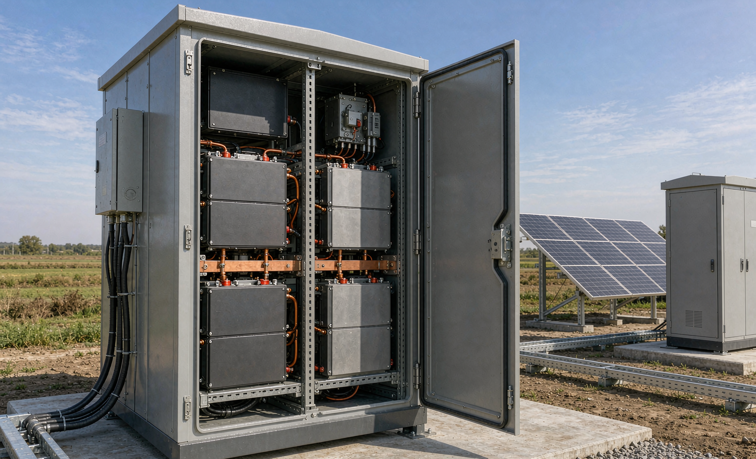
The current path is where cheap designs reveal themselves. Inside an enclosed cabinet with limited convection I size copper busbars at 3–4 A/mm², not the 6–8 A/mm² used for free-air conductors, and I require a measured temperature rise below 30 K at continuous rated current with the doors closed. Every bolted joint is specified with a target resistance under 0.05 mΩ, torqued to 8–12 N·m for M8 hardware with a recorded value, and re-torqued after the first thermal cycling sequence. Belleville washers on every module terminal, because sodium-ion cabinets see wide daily temperature swings and plain washers relax. String protection uses aR or gPV semiconductor fuses rated for the full DC bus maximum, with breaking capacity verified against the calculated prospective short-circuit current: a 90 kWh cabinet with 12 mΩ total path impedance can deliver over 20 kA, and a fuse chosen on continuous rating alone will fail catastrophically instead of clearing.
Thermal Design for Uncontrolled Ambient Sites
A microgrid cabinet sitting in open sun is a thermal problem before it is an electrical one. At 0.5C a sodium-ion pack generates roughly 25–40 W of heat per kWh installed, so a 90 kWh system dissipates 2.2–3.6 kW during a hard discharge. My default is filtered forced-air with an IP54 enclosure for temperate sites, moving to a sealed IP55 enclosure with an air-to-air heat exchanger wherever dust, salt, or livestock are present. Sealed always costs more airflow efficiency, so I model it rather than assume it. The genuine advantage of this chemistry is at the cold end: good sodium-ion cells retain 80–88 % of rated capacity at −20 °C, where LFP typically holds 55–70 %. That difference often removes the cabinet heater entirely, which removes a parasitic load, a control loop, and a failure mode. I still gate charging below 0 °C conservatively until the specific cell’s low-temperature charge acceptance is verified by test, not datasheet.
BMS Architecture and the Balancing Budget
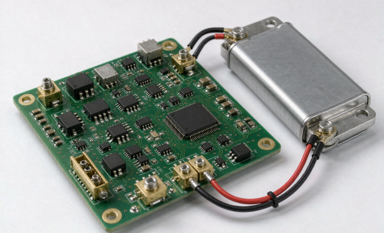
Sodium-ion needs a purpose-built BMS, not a reflashed lithium one. Two design consequences dominate. First, the measurement range must cover a per-cell window down to 1.5 V, and many lithium-oriented analog front ends specify accuracy only above 2.0 V, so their error grows exactly where the system is most vulnerable. I require ±5 mV accuracy across the full window, verified across the operating temperature range. Second, balancing must be sized against the slope. Because voltage moves quickly with SoC, a given millivolt spread represents less charge imbalance than it would in LFP, so passive balancing at 50–150 mA is usually sufficient for a 100 Ah class module. Balancing current must be traded against self-heating in a sealed enclosure. I also require the BMS to log per-cell minimum and maximum voltage, module temperature, and cumulative throughput, because on an eighteen-month service interval that log is the only diagnostic evidence available.
Protection Layers That Must Stay Independent
I design four protection layers and I write independence into the specification. Layer one is BMS firmware with over-voltage, under-voltage, over-current, and over-temperature thresholds. Layer two is a secondary protection device on a separate silicon die with its own reference and its own sense path. Layer three is the string fuse. Layer four is the mechanical disconnect and, on larger systems, the contactor drive interlock. The rule I never relax: no two layers may share a voltage reference, a sense wire, or a supply rail. I have investigated a field incident where firmware protection and secondary protection both read the same divider network, and a single cracked solder joint disabled both simultaneously. Independence is verified by fault injection during design validation, not asserted in a datasheet. I ask for the injection log and the pass criteria in writing.
Mechanical and Enclosure Design for Field Service
Design for the technician who arrives alone with hand tools. I cap module mass at 25 kg where a single person will handle it, or I specify rack rails and a lifting handle above that. Sense harnesses use keyed, polarity-protected connectors so a module cannot be reinstalled wrongly. Modules are addressable and hot-swappable at string level after isolation, with terminal covers that stay attached. I require IP rating verification after the vibration and shock sequence rather than before, following IEC 60068-2 profiles, because a gasket that passes on a new enclosure often leaks after transport. Cable entry glands face downward, drip loops are drawn on the assembly drawing rather than left to site practice, and the enclosure structure is 2–3 mm steel where it carries load. Finally I specify a clear internal service label area kept free of components, because every field engineer eventually needs somewhere to write.
Design Validation Gates and Governing Standards
A design is not finished when the drawings are released. I run three gates. Gate one is component level: cell qualification against IEC 62619 and UN38.3 transport testing, plus my own 0.5C capacity and 1 kHz resistance distribution on a 30-cell sample. Gate two is module level: thermal cycling, vibration to IEC 60068-2 profiles, insulation resistance above 1 MΩ, and a 500 VDC hipot. Gate three is system level: full-power charge and discharge at the temperature extremes, protection fault injection, IP verification after mechanical stress, and enclosure fire and hazard assessment informed by UL 9540A test data and NFPA 855 separation requirements. Grid-interactive behaviour is bounded by IEEE 1547 at the interconnection, which constrains the converter more than the battery, but the battery must supply the ride-through current the converter promises. Any change to cell, BMS safety logic, or barrier material after these gates reopens the affected gate. That is a written change-control rule, not a judgement call.
The Design Package I Expect From a Supplier
When evaluating a supplier for a custom battery solution, I ask for eight documents before discussing price. A cell datasheet with the full voltage window and low-temperature charge acceptance curves. A UN38.3 test summary tied to the exact bill-of-materials revision. An IEC 62619 report for the module configuration being quoted. A protection independence matrix plus the fault injection log. Busbar current density calculations with measured temperature rise at rated current. A thermal model or test data at the site’s design ambient. Torque and joint resistance specifications with recorded values from the first article. And a change-control register. A supplier who can produce all eight is engineering a system; a supplier who sends a glossy brochure and a price is assembling boxed cells. That distinction has decided every sodium-ion battery and lithium battery project I have signed off, and it is the cheapest due diligence available.
Frequently Asked Questions
What voltage window should a sodium-ion microgrid battery be designed to?
Design to the cell’s full stated window, commonly 4.0 V down to 1.5–2.0 V per cell, and then confirm the power converter accepts that full range at rated power. A 96-series string can swing roughly 192–384 V. Specifying the converter from nominal voltage is the most common error I correct.
Can I reuse a lithium battery BMS design for sodium-ion?
Not directly. Most lithium analog front ends guarantee accuracy only above about 2.0 V per cell, and sodium-ion operates well below that. You need ±5 mV accuracy across the full window, revised protection thresholds, and balancing resized for the sloping voltage curve. Reflashed firmware on lithium hardware is a false economy.
How much thermal management does a sodium-ion microgrid cabinet need?
Budget 25–40 W of heat per installed kWh at 0.5C. Filtered forced air in an IP54 enclosure suits temperate sites; dusty, salty, or agricultural environments justify a sealed IP55 enclosure with an air-to-air heat exchanger. Cold-climate sites often need no heater at all, which is a genuine chemistry advantage.
What depth of discharge should the design assume?
I design the pack for 90 % depth of discharge and expose 80–85 % as usable, holding buffers at both ends. The top buffer protects against balancing overshoot; the bottom buffer preserves reserve for the microgrid controller. Expect 3,000–5,000 cycles to 80 % state of health under those conditions.
How long does a custom sodium-ion design take?
From confirmed load data to a validated system, plan sixteen to twenty-four weeks. Roughly four weeks for architecture and sizing, six to eight for module design and first articles, and six to ten for the three validation gates. Certification against IEC 62619 dominates the tail, so start cell qualification first.
Closing Note
Sodium-ion is not a drop-in replacement for a lithium battery pack, and treating it as one is how good projects go wrong. It is a chemistry with a different voltage curve, a better cold-temperature story, a modest energy-density penalty, and a genuinely useful zero-volt transport tolerance. Design around those properties from the load profile forward and the result is a microgrid battery that a technician can service twice a decade. Design around a copied lithium architecture and you will spend the savings on site visits. If you are scoping a battery solution for a microgrid, send me the load data first — everything else follows from it.
Karl Huang is a Senior Lithium Battery Engineer specialising in sodium-ion, semi-solid-state, and lithium-ion system design for microgrid, telecom, and home energy storage applications.