Home Energy Storage Safety for Cabins
I have spent more than a dozen years designing and certifying lithium battery packs, and the hardest installations I have ever signed off on were not grid-tied suburban garages. They were cabins. A remote cabin breaks almost every assumption baked into a typical home energy storage system: nobody is on site to smell the first wisp of electrolyte vapour, the nearest fire response is forty minutes away, the grid connection may not exist at all, and the enclosure has to survive -30 °C in February and 38 °C in July in the same calendar year. When a customer asks me about home energy storage safety cabins, I stop talking about kilowatt-hours and start talking about failure modes.
This guide is written for the off-grid and weak-grid cabin owner, and for the contractors who wire them. It covers the eight failure modes I have actually investigated in the field — low-temperature lithium plating, thermal propagation in small combustible structures, wildfire ember intrusion, lightning and surge exposure, silent faults in unattended systems, generator back-feed, seasonal idle storage, and wildlife damage — and the specific clauses in UL 9540, UL 9540A, UL 1973, NFPA 855, IEC 62619 and the NEC that govern each one. I will also explain where a custom battery solution and a properly configured BMS solution earn their cost, and where they do not.
One thing up front: a home energy storage battery is not a generator with fewer moving parts. It is a stored-energy device that can release its entire energy content in minutes if it is abused, and the engineering controls that prevent that are not optional. Every serious incident I have reviewed traced back to a control that someone decided was inconvenient — a charge cut-off disabled so a cabin would “top up anyway,” a clearance shrunk to fit a wall, a surge protector deleted to save a hundred dollars.
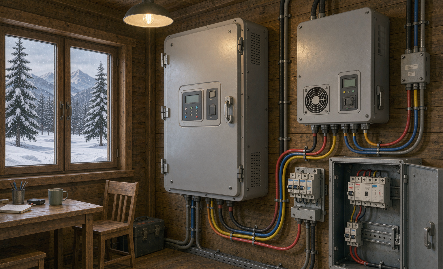
Why Cabin Sites Break the Assumptions Behind Most residential battery storage Designs
Most residential ESS products are designed and certified against a predictable use case: a conditioned or semi-conditioned space, an occupied dwelling, grid voltage that stays within ANSI C84.1 Range A (114–126 V at the service for a nominal 120 V supply), ambient temperatures between roughly 0 °C and 40 °C, and a human being within earshot of the alarm. A weekend cabin satisfies none of these.
Consider what changes. The ambient range widens to -30 °C … +40 °C. The grid disappears, so the inverter, not the utility, sets voltage and frequency — which means inrush, harmonic distortion and transfer behaviour become the owner’s problem. Occupancy drops from 90 % to perhaps 8 %, so a slow-developing fault has weeks to progress undetected. Mounting surfaces are often dimensional lumber rather than masonry or gypsum, which changes the fire dynamics entirely. And the AHJ (authority having jurisdiction) may have no ESS inspection checklist at all, which sounds like freedom until an insurance adjuster reads the installation photographs after a loss.
From a battery pack design standpoint, the three variables I design against are thermal window, duty cycle, and service interval. Cabins compress all three: a system that cycles deeply for four days in January and then sits at partial state of charge for three weeks behaves very differently from a daily solar self-consumption battery.
The Four Specifications I Refuse to Compromise On
- Cell chemistry and its thermal onset data. LiFePO4 (LFP) cathodes show thermal runaway onset roughly 100 °C higher than layered nickel-manganese-cobalt oxide chemistries, with separator shutdown at ~135 °C (polyethylene) and melt-through at ~165 °C (polypropylene). For an unattended wooden structure, that margin is the single cheapest safety upgrade available.
- A listed complete system, not a collection of listed parts. UL 1973 covers the battery; UL 1741 covers the inverter; UL 9540 covers the assembled system including the thermal and communication interfaces between them. Only the third one tells you the combination has been evaluated.
- Low-temperature charge inhibition that cannot be casually overridden. More on this in the next section.
- Remote telemetry that reaches a phone, not just a wall display. An alarm that only sounds inside an empty cabin is decoration.
Cold-Climate Charging: The Lithium Plating Trap and How a BMS Solution Prevents It
If I had to pick one failure mechanism responsible for the majority of premature cabin battery failures, it is lithium plating during low-temperature charging. When you push current into a graphite anode below roughly 5 °C, the intercalation kinetics slow down faster than the charge transfer kinetics, and metallic lithium begins to deposit on the anode surface instead of inserting between the graphene layers. That metallic lithium is partly irreversible, and worse, it can grow as dendrites that eventually pierce the separator and create an internal short.
The practical field data: at -20 °C a typical LFP prismatic cell delivers 60–70 % of its 25 °C discharge capacity and its DC internal resistance roughly doubles to triples, which is why a system that comfortably ran a 3 kW load in September sags and drops the inverter at -18 °C in February. Charging is far more dangerous than discharging, because discharge warms the cell and charge does not.
A competent BMS solution for a cold cabin does four things, in this order:
- Hard charge inhibit below 0 °C. Not a warning — a gate on the charge MOSFET or contactor. UL 1973 and IEC 62619 both require evaluation of charging at manufacturer-declared temperature limits, and IEC 62619 clause 7.2.2 specifically addresses charging temperature limits under both normal and abnormal conditions.
- Tapered current between 0 °C and 10 °C. I typically program a warm-up band: no charge below 0 °C, 0.05C from 0–5 °C, 0.1C from 5–10 °C, and full rate only above 15 °C. That 0.05C band exists so the pack can accept a trickle from solar on a bright cold morning without plating.
- Active pre-heat with cell-level (not ambient) sensing. Silicone pad or film heaters at 30–60 W per module, controlled by the coldest cell thermistor, not by an air sensor. I have seen air sensors read 8 °C while the cells sat at -4 °C after a clear night of radiative cooling.
- Parasitic budget accounting. Self-heating consumes stored energy. On a 10 kWh system, 60 W continuous heating is 1.44 kWh/day — 14 % of nameplate. On a string of three cloudy days in January, that is the difference between keeping the water pump running and a frozen pipe.
Discharge at low temperature is safe down to about -20 °C for most LFP cells (IEC 62619 and manufacturer data sheets typically list -20 °C discharge / 0 °C charge), but I derate continuous current by 30–40 % below -10 °C to keep the sag under the inverter’s low-voltage disconnect, and I set the low-voltage cut-off to protect against bumping the inverter off mid-cycle repeatedly.
Thermal Runaway, Fire, and Clearance Rules: UL 9540, UL 9540A and NFPA 855 in Small Structures
NFPA 855 (Standard for the Installation of Stationary Energy Storage Systems) is the document your AHJ will cite, and UL 9540A (Test Method for Evaluating Thermal Runaway Fire Propagation) is the test method that generates the data NFPA 855 acts on. Understanding the division of labour helps: UL 9540A does not “approve” anything; it produces a report at four levels — cell, module, unit, and installation — quantifying whether thermal runaway propagates, how much combustible gas is generated, and what the maximum surface temperatures are.
For cabins, the two outcomes that matter are (a) whether the unit-level test showed no propagation beyond the initiating module, and (b) whether the installation-level test, if performed, imposed separation distances or fire suppression requirements. Where a manufacturer has no UL 9540A report, NFPA 855’s default separation and fire-protection provisions apply, and those defaults were written with garages and utility rooms in mind, not 4 m × 5 m pine-lined rooms.
Clearances I Actually Enforce on Cabin Jobs
- Separation between ESS units: follow the listing and NFPA 855 Chapter 7; where the report is silent, I use 3 ft (914 mm) between units and never stack combustibles in that gap. Firewood does not belong beside a battery.
- Working clearance: NEC 110.26 working space applies to equipment that may need examination or service — for a 0–150 V-to-ground system, 3 ft in front of the equipment. I keep it even on 48 V systems, because the day you need it is the day something is wrong.
- Combustible surfaces: mount to non-combustible backing where possible. If the wall is dimensional lumber, I install a cement-board or steel backing plate, because a listed enclosure is tested against defined boundary conditions, and a wooden wall is not one of them.
- Detection: NFPA 855 requires listed smoke or fire detection in the ESS room, interconnected to the dwelling alarm system where the structure is occupied. In an unoccupied cabin, that means a monitored or cellular-connected detector, or the requirement is satisfied on paper only.
- Gas and ventilation: venting lithium cells release hydrogen, carbon monoxide, carbon dioxide, methane, ethylene and hydrogen fluoride. HF is the one that sends people to hospital. Do not vent an ESS enclosure into an occupied sleeping space, and do not rely on a room’s natural infiltration.
One more note for anyone considering a do-it-yourself pack for a cabin. A DIY assembly will not carry UL 9540, and NFPA 855 is explicit that ESS shall be listed. Beyond the code issue, an untested battery pack design has no validated propagation data, so the thermal barrier between modules, the cell spacing, and the vent path are all guesses. I have built plenty of prototype packs in my career; none of them went into a building someone slept in without a listing.
Wildfire and Ember Exposure: Defensible Space and Ember-Resistant Enclosures
The wildland-urban interface is where most of the cabins I work on now sit, and ember intrusion — not the flame front — is what burns them. Wind-borne embers in the 0.5–3 mm range travel a kilometre or more ahead of a fire and find every unsealed penetration in a structure. If your ESS enclosure has an intake louver or a cable entry that an ember can enter, you have built an ignition point into your power system.
The mitigation is unglamorous and cheap: 1.6 mm (1/16 in) or finer corrosion-resistant metal mesh on every vent opening; ember-resistant vent assemblies (evaluated to the ember intrusion test in ASTM E2886) where the enclosure is vented to outdoors; gasketed or hub-type cable entries rather than open knockouts; and a non-combustible skirt at the base of the enclosure. I also specify that the ESS be mounted on the side of the structure away from the prevailing upslope wind, because the windward wall is the ember collector.
Defensible-space rules from NFPA 1144 — roughly 30 ft of lean, clean and green to 100 ft of reduced fuel, adapted to local WUI code — apply to the whole site, not just the cabin. Where the ESS sits outdoors on a pad, I require a 10 ft non-combustible ring, because the fire service will not defend a battery with a sagebrush skirt. And if you are in a jurisdiction enforcing the International Wildland-Urban Interface Code, the ignition-resistant construction requirements extend to attached equipment enclosures; check before you hang a battery on an exterior wall.
Lightning, Surges, and Grounding on Exposed Sites
Cabins sit on ridges, on lake points, and next to the tallest tree in the draw. That is precisely where you should not put twenty kilowatt-hours of sensitive power electronics without a surge plan. IEC 62305 provides the risk-management framework (four protection levels, LPL I–IV, based on a rolling-sphere or mesh analysis of the structure), and the practical implementation is layered surge protection plus a competent grounding electrode system.
What I install, in order of energy handling:
- Type 1 SPD at the service or transfer-switch input (the point where the AC enters the building), rated to discharge the expected partial lightning current, with a voltage protection rating as low as practicable — I want VPR ≤ 900 V on 120/240 V systems, ≤ 600 V where the inverter manufacturer’s withstand allows.
- Type 2 SPD at the ESS and inverter AC bus, per IEC 61643-11 or UL 1449, with lead lengths kept under 0.5 m. Lead length, not device rating, is the usual reason a “protected” installation still loses equipment: 1 m of lead adds roughly 1000 V of inductive kick per kA per microsecond.
- DC-side SPDs on the PV array and on the battery DC bus where the DC cable run exceeds about 10 m or is routed outdoors. DC arcs do not self-extinguish at zero crossing the way AC arcs do, which is why DC overcurrent and surge protection deserves separate attention.
- Signal and antenna protection on the cellular or satellite link that carries your remote monitoring. I have replaced more monitoring gateways killed through their antenna than through their power supply.
Grounding electrode resistance: NEC 250.53 requires a supplemental electrode where a single rod exceeds 25 Ω. On rocky ridge-top soils, 25 Ω is often unreachable with one rod, so plan for two rods at least 1.8 m apart, or a ground ring, or a concrete-encased electrode. Above 2000 m elevation — common for mountain cabins — apply the IEC 60664 clearance and creepage correction factors for reduced air density; the same air gap that is safe at sea level will break down sooner at altitude, and convective cooling is weaker too.
Unattended Operation: Remote Monitoring and Failing Into a Safe State
Unattended is the defining condition of a cabin, and it changes the engineering question from “will this fail?” to “when this fails, what does it fail into?” Three monitoring channels carry most of the diagnostic value:
- Cell voltage delta. A healthy LFP pack sits within 20–40 mV across cells at rest and within 60–100 mV under a 0.5C load. A cell drifting beyond ~150 mV from the mean is telling you about a balancer fault, a high-resistance interconnect, or an incipient internal short. Set the alarm, not the trip, at 200 mV.
- Insulation resistance to chassis (IMD). IEC 62485 requires insulation monitoring on unearthed battery systems, with a commonly applied threshold around 100 Ω per volt of nominal system voltage. A 48 V nominal system therefore alarms below roughly 4.8 kΩ. In practice the first thing that drops insulation resistance in a cabin is condensation, not a damaged cell.
- Charge-throughput vs. coulomb-count drift. Every BMS that estimates SoC by coulomb counting drifts, and the drift accelerates when a pack sits at low currents for weeks. Force a full-charge absorption event at least monthly to re-anchor the SoC, and log it.
Fail-safe behaviour is the other half. A cabin home battery backup system should drop the non-critical loads and hold the critical loads when telemetry is lost or a fault is flagged: open the contactor on ground fault, on cell overvoltage, on charge inhibit violation, and on internal communication loss. The one failure mode I will not accept is a contactor that welds closed with no secondary protection, which is why I specify a properly rated DC fuse or breaker in series plus a pyrotechnic or shunt-trip layer on larger systems.
Generators, Inverters, and the Transfer-Switching Hazards Nobody Warns You About
Almost every off-grid cabin has a generator, and the generator is where the dangerous mistakes live. Three of them, specifically.
Back-feed. A generator connected to the building without a listed transfer switch or a mechanical interlock can energise the utility line, or fight the inverter for control of the bus. I have seen an inverter’s AC output destroyed in under a second by being paralleled with a running generator. The fix is a listed transfer switch with a mechanical interlock — no cords, no suicide plugs, no exceptions.
Neutral-to-ground bonding. A generator with a bonded neutral feeding a system that already has a service bond creates a second neutral-to-ground connection and puts objectionable current on the equipment grounding conductor. Most inverter-chargers switch the bond internally, which is why the generator’s bond must be removed or a switched-neutral (3-pole vs 4-pole) transfer scheme used. Get this wrong and you will chase ground-fault trips for a season.
Charge current and waveform. Cheap portable generators produce total harmonic distortion well above 6 % and unstable frequency under load, and inverter-chargers are sensitive to both; they will derate, drop, or cycle on and off. Set the charger’s AC input current limit so the generator runs at 60–80 % of its continuous rating — a 7 kW generator should not be asked to supply the loads and a 6 kW charge simultaneously. I routinely programme a 20 A AC input limit on cabin systems even when the charger can pull 50 A.
Seasonal Idle: Winterisation, State of Charge, and Rodent Damage
Seasonal cabins spend most of the year idle, and idle is not benign. LFP cells self-discharge at roughly 1–3 % per month at 20 °C including BMS quiescent draw, faster when warm and slower when cold — but the BMS and telemetry board keep drawing regardless. A pack left at 15 % SoC in October will be below low-voltage cut-off by March, and once cells drop below about 2.0–2.5 V the copper current collector can dissolve and re-plate on the anode, creating internal shorts on the next charge.
My winterisation procedure for a seasonal cabin:
- Leave the pack at 40–60 % SoC. That is high enough to ride out self-discharge, low enough to minimise calendar ageing, and — critically — below the state of charge at which a thermal event releases the most energy.
- Confirm the charge-inhibit temperature logic is live, then verify with an actual cold start, not a bench test.
- Leave the system energised but with the main contactor open, or on a maintainer if solar is available. Never leave a pack connected to a solar array with no charge controller in circuit.
- Photograph the cell voltage spread and insulation resistance before you leave. Those two numbers are your baseline for spring commissioning.
Rodents are the other seasonal hazard, and they are attracted to warm enclosures and, in some formulations, to soy-based wire insulation. Use metal-clad or conduit-protected cable for every run, fit 3 mm mesh over every vent, seal conduit entries, and keep the enclosure skirt tight to the pad. I have opened spring enclosures with a nest built directly on the BMS heatsink, which is both a fire hazard and a corrosion problem, since rodent urine is conductive and aggressively corrosive to copper.
Commissioning Checklist for a Remote Cabin Installation
- Transport check. Cells and packs ship under UN 38.3 (tests T1–T8) and, for air freight, at ≤ 30 % state of charge per IATA DGR for UN3480. Gravel-road transport is a vibration test your cells never asked for: inspect torque on every terminal to the manufacturer’s specification before energising.
- Mechanical and environmental. Verify IP rating of the enclosure (IEC 60529; IP54 minimum indoors, IP65 or NEMA 250 Type 3R outdoors), confirm the condensation management strategy, and check that snow will not bury the air intake.
- Electrical. Torque-audit all DC connections, verify insulation resistance to chassis (≥ 100 Ω/V per IEC 62485 practice), confirm DC overcurrent device ratings exceed the maximum prospective short-circuit current available from the pack, and hipot at 2U + 1000 V AC where the standard applies.
- Controls. Force each protection to trip at least once: overvoltage, undervoltage, overcurrent, over-temperature, low-temperature charge inhibit, ground fault.
- Telemetry. Confirm the off-site alert path works by triggering a simulated alarm and verifying the message reaches a phone outside the local network.
- Documentation. Leave the UL 9540/UL 9540A documentation, the single-line diagram, the torque values and the emergency response guidance inside the structure. The first responder who arrives at 2 a.m. needs to know what is on the wall and how to isolate it.
That last item is the one most often skipped and the one that matters most, in my experience. Everything else in this guide protects the building; the documentation protects the people who come to help.
Frequently Asked Questions About Home Energy Storage Safety for Cabins
Can I install a home energy storage battery in an unheated cabin that drops to -25 °C?
Yes, with conditions. Discharging LFP cells down to -20 °C is generally within manufacturer limits; charging below 0 °C is not, and must be blocked by the BMS or by a self-heating system that warms the cells above 5 °C before accepting current. Budget the heating energy — 30–60 W per module running continuously through a cold snap is a real fraction of a small system’s capacity — and size the array accordingly.
How far does NFPA 855 require my battery to be from a wood stove or propane appliance?
NFPA 855 does not give a single number for every case; separation depends on the listing, on the UL 9540A results, on whether the system is indoors or outdoors, and on the ESS fire-protection provisions adopted in your edition. What I do in practice is keep the ESS out of any room containing a solid-fuel or gas appliance, maintain the manufacturer’s listed clearances as an absolute floor, and never place the unit where a flue or appliance service access is shared. Ignition sources and stored energy belong in different rooms.
Do I need a UL 9540A report for a small off-grid cabin system?
Your AHJ decides what it needs, but the report is the document that lets a small installation avoid NFPA 855’s default separation and suppression requirements. If a manufacturer cannot produce a UL 9540A report at the unit level, assume the conservative defaults apply — and price the enclosure and clearance accordingly before you frame the room.
What state of charge should I leave the system at when I close the cabin for the winter?
40–60 %, with the main contactor open and the charge-inhibit logic verified live. Do not leave it at 100 % (maximum stored energy, accelerated calendar ageing) and do not leave it at 15 % (self-discharge will take it below cut-off and the cells will be damaged before you return).
Can I charge the battery from a portable generator?
Yes, through a listed transfer switch or the inverter-charger’s AC input, with the charger’s input current limited to 60–80 % of the generator’s continuous rating. Use an inverter generator if you can; conventional portable units with high harmonic distortion and unstable frequency cause repeated charger drop-outs that owners misdiagnose as battery faults. Never parallel a generator with the inverter output without equipment specifically designed for it.
Will lightning destroy a system on an exposed ridge?
It can, and usually through the antenna or the DC runs rather than the AC service. Layer Type 1 and Type 2 SPDs, add DC-side protection on runs longer than about 10 m, protect the monitoring antenna, and invest in a low-resistance grounding electrode system — two rods or a ring in rocky soil. Keep SPD leads short, because lead inductance defeats the device faster than an undersized rating does.
Does a 48 V system still need overcurrent protection and an enclosure?
Yes. A 48 V nominal LFP pack sits below the 60 V DC threshold where shock hazard becomes a primary concern, which simplifies some NEC requirements, but available short-circuit current from a large LFP pack is measured in thousands of amperes and DC arcs do not extinguish at a zero crossing. Properly rated DC overcurrent devices, a listed enclosure, and a single neutral-to-ground bond are all still required.