Home Energy Storage Grounding and Neutral Bonding for Backup Circuits
During the 2023 field season I commissioned more than forty residential battery systems, and the single fault that delayed the most inspections was not the cells or the inverter. It was the grounding and bonding around the backup circuits. A home energy storage system that loses grid power is supposed to keep the lights on, but if the neutral and ground are tied in the wrong place you get circulating currents, tripped breakers, and a real shock hazard. This article walks through how I set up grounding and neutral bonding for backup circuits on lithium battery storage, using the same methods we apply at Horizon Power when we ship a custom battery solution to an installer.
Why Backup Circuits Need a Dedicated Grounding Path
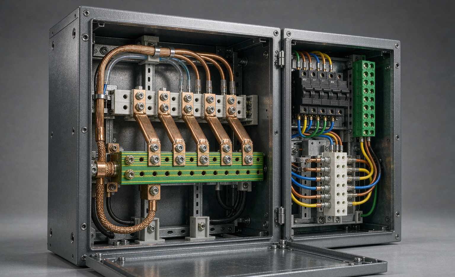
Most homes have a single service disconnect where the utility neutral is bonded to the grounding electrode conductor. When a home energy storage inverter forms a backup source, it becomes a separately derived system. The backup panel must have its own bonding jumper between the neutral and the ground bus, because the inverter output is isolated from the utility until the transfer switch operates. If you skip this, metal enclosures can float at line potential during an outage, which is exactly when someone will be working near the panel. I have seen a well pump frame read 120 volts to ground simply because the bond was missing at the battery disconnect.
The fix is not exotic. It is discipline. Every backup load center that receives power from a battery inverter gets one bonding jumper, installed at the first disconnecting means, and nowhere else. The grounding electrode conductor then ties that local ground bus to the same earth electrode the utility uses. The lithium battery itself sits in an enclosure whose chassis is bonded to that same bus, so a fault inside the pack trips the breaker instead of energizing the cabinet skin.
Separately Derived Systems and the Bonding Jumper
Under the NEC, any inverter that galvanically isolates the output is treated as a separately derived system. Article 250.30(A) requires a bonding jumper from the derived system neutral to the grounding electrode conductor at the first disconnecting means. In a typical home battery install, that first means is the backup load center. We size the bonding jumper using Table 250.102(C)(1): for a 10 kW inverter fed by 4 AWG conductors, the jumper is normally 8 AWG copper, but we step up to 6 AWG when the run exceeds three meters.
The point is not the exact gauge. It is that the bond exists exactly once, at one defined location, so that fault current has a single clear return path to source. When I train installers I tell them to photograph the jumper before closing the panel, because a missing bond is invisible once the cover goes on. A home energy storage project that passes inspection on paper but lacks this jumper will fail the first real fault.
Transfer Switches and Neutral Position
A common mistake is bonding the neutral at both the utility service and the inverter. During normal operation the transfer switch connects the backup panel to utility neutral. When it switches to battery, the inverter supplies neutral through its own internal transformer. If both ends are bonded, neutral current splits between the two paths and the equipment grounding conductor carries return current, which violates 250.6(A) and heats the conduit.
The fix is a switched neutral transfer switch or an inverter configured for a solidly derived neutral. I always verify with a clamp meter that no current flows on the ground bus during a transfer test. If I see more than a few milliamps on the equipment grounding conductor while the inverter is carrying load, I know a double bond exists and I trace it before continuing. This single check has caught more wiring errors than any other step in my commissioning routine.
Grounding Electrode System and Conductor Sizing
The grounding electrode conductor connects the system to earth through the existing electrode, usually the service ground rod or the structural rebar. For home energy storage we do not add a second rod unless the existing one fails the 25 ohm test in 250.53(A). The conductor itself is sized from Table 250.66 by the largest ungrounded conductor. A 70 A home battery inverter on 4 AWG typically needs a 4 AWG grounding electrode conductor when the enclosure is a meter away from the service.
We keep all bonding surfaces bright and use anti-oxidant paste on aluminum, because a high resistance bond is worse than no bond at all. I torque every grounding lug with a calibrated wrench and write the value on the panel schedule. The lithium battery enclosure, the inverter chassis, and the backup panel all land on the same equipment grounding conductor, which is sized to carry the full fault current until the overcurrent device opens.
Sizing Conductors and Selecting Components
Backup circuits should be a dedicated sub-panel, not a handful of breakers pulled from the main. I load the panel at 80 percent of the inverter continuous rating. For a 10 kW unit that is 8 kW, so a 40 A backup feed at 240 V covers a refrigerator, furnace blower, well pump, and a few outlets. The lithium battery behind it needs to support the surge of the well pump motor; we specify a custom battery solution with a 3 C discharge rating for such loads.
Conductor selection matters as much as the gauge. THHN in conduit for the feeder, proper bend radius, and lugs rated for the conductor. I avoid mixing tinned and bare copper on the same bus because the galvanic difference accelerates corrosion in humid basements. A battery storage installation that looks tidy on day one but corrodes in two years is a failure no matter how clean the code paperwork looks.
Commissioning and Verification Tests
Before I close the panel I run three checks. First, a continuity test from the neutral bus to the ground bus on the backup side confirms the bonding jumper is in place. Second, an insulation resistance test at 500 V DC between each ungrounded conductor and ground must read above 1 megohm. Third, a live transfer test: with the grid simulated as lost, the inverter must pick up the load within the listed switch time and the neutral to ground voltage must stay under 30 V rms.
Only after these three pass do I label the panel and hand the system to the homeowner with the IEEE 1547 settings documented. The label notes the bonding location, the grounding electrode path, and the maximum backup load. A home energy storage owner who understands which circuits are backed up is far less likely to overload the inverter during a multi day outage, which protects both the equipment and the people relying on it.
Field Lessons From Real Installations
The patterns repeat. Older homes with knob and tube or upgraded only at the panel are the hardest, because the grounding path is inconsistent behind the walls. In those jobs I run a fresh equipment grounding conductor along the feeder instead of trusting the legacy wiring. Modular pack designs from a custom battery solution vendor also help, because the inverter and battery share a documented grounding scheme rather than leaving the installer to infer it.
None of this is theoretical for me. I have been called back to systems that hummed, that tripped at midnight, and that gave a homeowner a small shock from a dishwasher frame. In every case the root cause traced to a grounding or bonding decision made in a hurry. Taking the extra hour to do it once, correctly, is the cheapest insurance in the whole home energy storage build.
What is the difference between grounding and bonding in home energy storage?
Grounding connects the system to earth to limit voltage from lightning and faults. Bonding joins metal parts together so they stay at the same potential, which prevents shocks. In a home battery backup you need both: a grounding electrode conductor to earth and a bonding jumper that ties the neutral to the ground bus inside the backup panel.
Do I need a separate ground rod for my backup battery?
Usually no. The NEC lets you connect the storage system to the existing grounding electrode system. You only add a supplemental rod if the original electrode fails the 25 ohm resistance test. Adding rods where they are not needed can create ground loops and make fault clearing worse rather than better.
Can I bond the neutral at both the utility and the inverter?
No. The neutral should be bonded in exactly one place. If you bond at the service and again at the inverter, neutral return current will travel on the equipment grounding conductor during a transfer, which is a code violation and a fire risk. Use a switched neutral or a properly derived inverter output instead.
How do I test grounding and bonding after installation?
Run a continuity check on the bonding jumper, an insulation resistance test above 1 megohm at 500 V DC, and a live transfer test that confirms the inverter picks up the load and keeps neutral to ground voltage under 30 V rms. These three steps catch most field failures before they become hazards.
What standards apply to home energy storage grounding?
In the United States the key references are NEC Article 250, Article 706 for energy storage systems, UL 1741 for the inverter, and IEEE 1547 for interconnection. At Horizon Power we also build to IEC 62109 for the power conversion equipment, because many of our custom battery solution projects ship to markets that reference IEC directly.
Further Reading
References