Semi-Solid State Battery Cell Stacking and Lamination
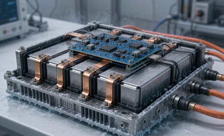
As a senior lithium battery engineer at Horizon Power, I have spent the last decade moving pouch and prismatic cells from the lab bench to fully automated production lines. When our team began building semi-solid state battery packs at volume, one process step surprised several of my colleagues: cell stacking and lamination. Most people focus on the electrode chemistry, but the way we stack and bond the layers determines whether a semi-solid state battery reaches its promised energy density or fails early from delamination and internal short circuits. In this article I share the practical engineering we use on our lines, including alignment tolerances, hot press parameters, and the inline checks that keep our lamination scrap below one per cent.
Why Stacked Construction Matters for Semi-Solid Cells
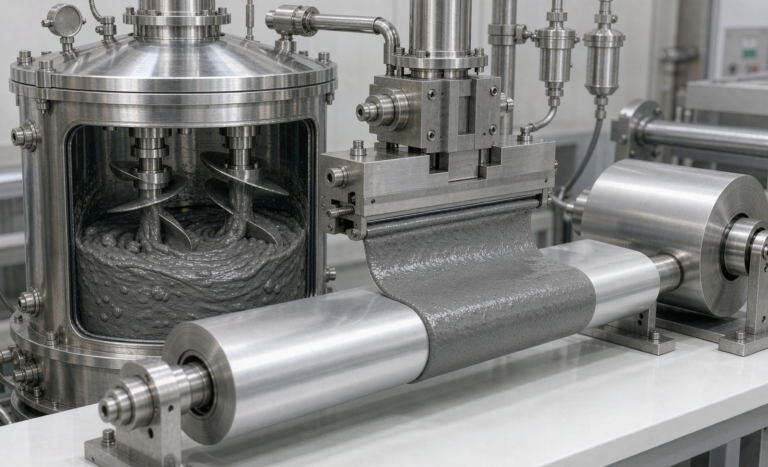
Stacked construction beats winding for thick, semi-solid electrodes. Our semi-solid cathode slurry is far thicker than a conventional lithium battery electrode, often 120 to 200 micrometers per side. A wound cell would develop bending stress that cracks the semi-solid coating and widens the gap between the separator and the electrode. Stacking lets us align flat, uniform layers and keep the interfacial pressure even across the whole cell. That even pressure is what allows the gel and semi-solid electrolyte to wet the electrode surface without trapping air. On our lines a stacked pouch format also trims dead space, which lifts pack-level energy density by roughly five to eight per cent compared with the same chemistry in a wound format. For applications where every gram matters, that margin is the difference between a viable product and a prototype.
Stacking also helps us manage the different mechanical behavior of semi-solid layers. A gel electrolyte does not flow into cracks the way a liquid does, so any defect we introduce during winding stays there for the life of the cell. With flat stacked layers we can inspect each sheet before it goes into the stack, and thermal expansion during lamination stays in-plane instead of curling the electrode around a mandrel. In my experience that single change removes a whole family of field failures that used to show up only after six months of cycling.
Stacking Sequence: Cathode, Separator, Anode
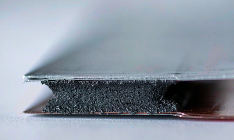
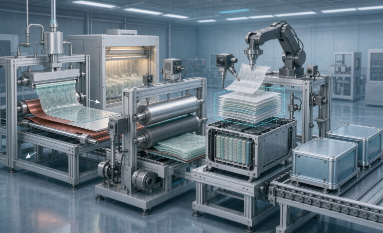
The core of every cell is a repeating stack of cathode, separator, separator, and anode. We run a Z-fold or stacked-sheet layout where a single long separator is folded between the positive and negative electrodes so the two never touch directly. The order matters. We place the cathode first because its coating is the most sensitive to particle contamination, then the separator, then the anode. Inline vision confirms each layer sits within a plus or minus 0.3 millimeter window before the next sheet is placed. If a layer is off, the stacker rejects it and the pick-and-place arm resets. We have found that discipline saves far more material than trying to recover a misaligned stack downstream. The semi-solid layers are also less forgiving than liquid electrolyte cells, because a trapped void becomes a hot spot during fast charge.
Lamination Methods: Hot Press Versus Roll-to-Roll
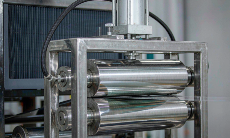
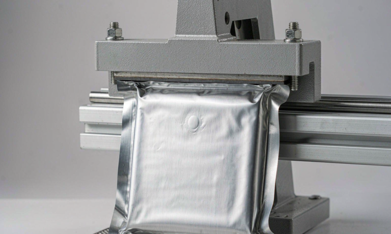
Two lamination routes dominate our pilot and production lines. The first is hot press lamination, where the finished stack is placed between heated platens at 60 to 90 degrees Celsius and pressed at 0.2 to 0.5 megapascal for 30 to 90 seconds. Heat softens the binder and the gel electrolyte, letting the layers fuse into a single, void-free component. The second is roll-to-roll lamination, where the electrode and separator webs pass through a heated nip roller. Roll-to-roll is faster and suits thinner formats, but it is less tolerant of the thick semi-solid coatings we use. We reserve hot press for prismatic and high-capacity pouch cells and roll-to-roll for smaller custom battery solution formats where throughput wins over absolute density. Selecting the wrong method is the most common cause of uneven adhesion I see in new lines.
Adhesion, Voids, and Electrolyte Wetting
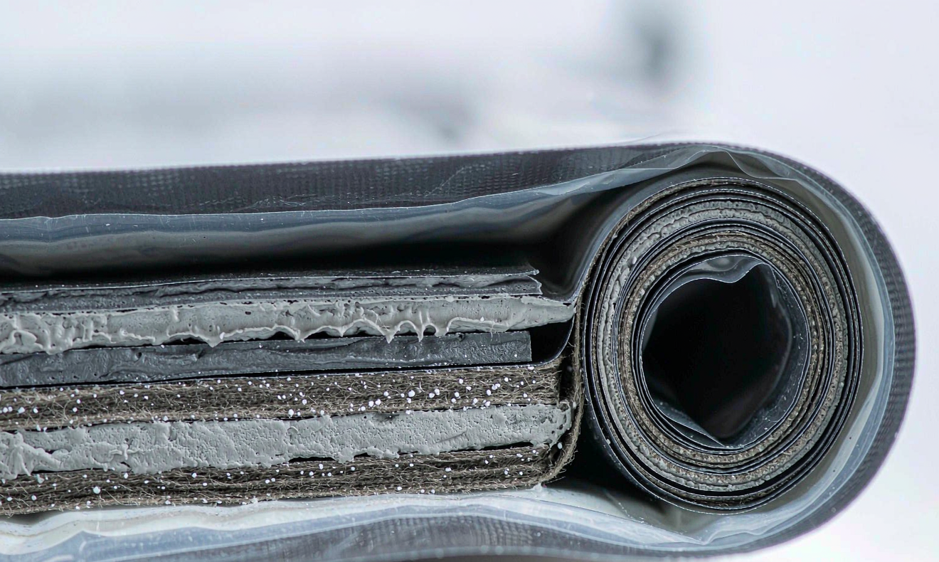
A good laminate shows uniform adhesion with no visible bubbling and no dry patches. We measure peel strength at the electrode-separator interface and target at least 1.5 newtons per centimeter after conditioning. Voids are the enemy. Any air pocket trapped during lamination blocks ionic pathways and grows during cycling. We degas the semi-solid layers under vacuum before lamination and hold a slight positive pressure during the hot press to push remaining gas out to the edges. Electrolyte wetting is the final gate. After lamination we soak the stack and verify that the gel electrolyte has penetrated every channel using a dielectric impedance check; a healthy stack shows a tight, low spread of resistance values across all cells in a lot.
Common Lamination Defects and How We Prevent Them
The three defects we watch most closely are wrinkles, edge delamination, and tab damage. Wrinkles come from uneven web tension on roll-to-roll lines; we control them with a dancer roller and closed-loop tension feedback rather than by slowing the line. Edge delamination appears when the gel electrolyte or adhesive fails to reach the outer two millimeters of the stack, usually because a dispensing mask drifted out of position. Tab damage shows up as a small tear near the terminal where the stacking head gripped the foil too hard. We redesigned that gripper with a soft polymer pad and the defect rate dropped from roughly 800 parts per million to under 100. Each defect has a different root cause, so we never fold them into a single quality number. On a semi-solid state battery line the cheaper fix is almost always at the station that created the defect, not at final inspection.
Alignment Tolerances and Inline Inspection
Precision is not optional. We hold electrode-to-separator alignment to plus or minus 0.3 millimeter and keep the overall stack height variation under 1 per cent. To hold that, every stacker carries a top and bottom camera that reads fiducial marks printed on the electrode tabs. The data feeds a closed-loop stage that corrects drift in real time. After lamination we run an automated X-ray or ultrasonic scan on a sample basis to catch internal folds and edge delamination that vision cannot see. When a lot drifts past tolerance, the line stops and we recalibrate rather than shipping suspect cells. That habit is why our field return rate on stacked semi-solid state battery packs stays below our internal target.
Throughput, Yield, and Scale-Up
Moving from a pilot line to a gigawatt-hour line changes the math. A single stacking head places roughly 0.5 to 1.0 layers per second, so a 60-layer cell takes about one to two minutes per stack before lamination. To hit volume we run parallel heads and balance them so no single station becomes the bottleneck. Yield is won in the small steps: clean-room humidity below 1 per cent relative, electrode edges trimmed to a consistent kerf, and a laminator nip that is dressed daily. We track first-pass yield by shift and treat any drop below 95 per cent as a process alarm, not a cost of doing business.
Scale-up also changes how we think about fixtures. On a pilot line an engineer can adjust the press plate by feel; on a production line the fixture must hold uniform pressure across a stack that is twice as large, without an operator touching it. We moved to servo-driven pressing plates with load cells at each corner, which lets the controller trim pressure in real time as the gel electrolyte softens. That one upgrade cut our thickness variation across a 400 by 300 millimeter stack from about 4 per cent to under 1.5 per cent, and it also shortened the lamination cycle because we no longer wait for a slow manual check between batches.
Frequently Asked Questions
What is cell stacking in a semi-solid state battery?
Cell stacking is the process of laying cathode, separator, and anode sheets into a precise alternating stack, then bonding them so the layers act as one component. In a semi-solid state battery the thicker electrodes make stacking preferable to winding because it keeps interfacial pressure even and avoids coating cracks.
How does lamination differ from winding?
Winding rolls a long electrode-separator assembly into a spiral, while lamination presses flat stacked layers together. Lamination suits thick semi-solid coatings and gives higher pack energy density, whereas winding is faster for thin, standard lithium battery formats.
What temperature and pressure work best for lamination?
On our lines hot press lamination runs at 60 to 90 degrees Celsius and 0.2 to 0.5 megapascal for 30 to 90 seconds. Thicker coatings need the higher end of that range, but exceeding it can smear the semi-solid layer and raise internal resistance.
How do you control voids during lamination?
We degas the semi-solid layers under vacuum before lamination and apply slight positive pressure during the hot press to push trapped air to the edges. Inline dielectric checks after lamination confirm the gel electrolyte has wetted every channel.
Which standards apply to stacked semi-solid cells?
Stacked cells must clear UN38.3 for transport, IEC 62133 for safety, and the relevant UL 1642 or UL 1973 requirements depending on format. Our drone battery and stationary products are also qualified against FAA and EASA documentation where applicable.
Can Horizon Power supply custom stacked cell formats?
Yes. We build stacked pouch and prismatic semi-solid state battery cells as a custom battery solution, with stacking geometry, layer count, and lamination profile tuned to the customer application and verified on our pilot line before volume.
Further Reading
References