Dendrite Suppression in Semi-Solid State Batteries
During a 2023 qualification run for a 24 Ah semi-solid state pouch cell, my team at Horizon Power watched capacity collapse from 98.5 percent to 71 percent in just 140 cycles. The root cause was not the cathode or the separator. It was lithium dendrite growth on the anode. For any engineer specifying a semi-solid state battery, dendrite suppression is the single most important reliability lever after thermal control. In this article I explain how dendrites form in semi-solid chemistry, and the practical design and formation steps we use to keep them from ever reaching the separator.
Why Dendrites Form in Semi-Solid Cells
A dendrite is a needle-like filament of metallic lithium that grows from the anode during charging. It forms when lithium ions plate as metal instead of intercalating into graphite or a lithium host. In a semi-solid state battery the electrolyte still contains a small fraction of liquid solvent, which keeps interfacial resistance low but also creates local pathways where lithium can deposit unevenly. The trigger is almost always overpotential: charging too fast, charging below about 5 degrees Celsius, or running the cell with an overly tight negative to positive electrode ratio.
In my experience the most common field failure is fast charging in cold weather. At sub-zero temperatures the lithium diffusion rate in the anode host drops by more than an order of magnitude, so lithium metal plates on the surface instead of inserting. Once a nucleus forms, it keeps growing along the path of least resistance, which in a stacked semi-solid cell is toward the solid electrolyte layer. The result is either a soft short that self-heals and quietly eats capacity, or a hard short that takes the cell out completely. This is why dendrite suppression has to be designed in, not hoped for.
Solid Electrolyte and Interface Engineering
The first line of defense is the electrolyte itself. Semi-solid cells use a composite of a solid polymer or oxide matrix with a small liquid wetting agent. We tune the ionic conductivity to above 1 milliSiemens per centimeter at room temperature while keeping the liquid fraction below roughly 10 percent by weight. A higher liquid fraction improves wettability but raises the dendrite risk, so the design is a balancing act between transport and safety.
Interface resistance matters just as much. A high interfacial resistance forces local current concentration, and concentrated current is exactly what seeds a dendrite. We apply a thin functional interlayer between the anode and the solid electrolyte to lower contact resistance and to give lithium a more uniform deposition surface. Measured by electrochemical impedance spectroscopy, a well-engineered interface shows a charge transfer resistance below 15 ohm centimeters squared, which is where we see plating risk drop sharply. A lithium battery with a clean, low-resistance interface is far more forgiving of minor charging abuse.
We also tune the anion coordination in the liquid fraction with a low-concentration lithium salt and a fluorinated solvent, so the reduction products form a stable interphase rather than a mixed, porous one. At 45 degrees Celsius the same cell shows roughly 30 percent lower interfacial resistance than at 0 degrees, which is why we specify an operating window of 0 to 45 degrees for most semi-solid packs.
Anode Protective Layers and Artificial SEI
The native solid electrolyte interphase that forms on lithium is brittle and cracks under cycling, which exposes fresh lithium and restarts plating. The fix we use is an artificial SEI: a dense, elastic layer of lithium fluoride, lithium nitride, or a thin oxide coating applied directly to the anode foil. This layer is mechanically strong enough to block filament penetration yet ionically conductive enough to let lithium pass.
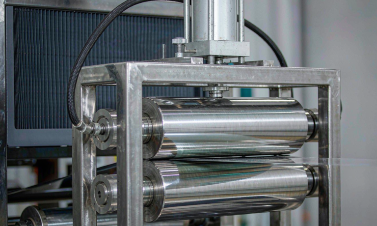
In production we deposit the layer by a roll-to-roll vacuum process so the thickness stays within a 20 to 60 nanometer window. Thinner than that and it cracks; thicker and it adds impedance. We validated the approach on a 12-cell pilot batch where artificial-SEI cells held 91 percent capacity after 500 cycles at 1C, while unprotected controls dropped below 80 percent by cycle 300. That is the kind of margin a custom battery solution needs to survive real duty cycles rather than a laboratory ideal. We also found that an optimized artificial SEI lets us safely cycle at 2C for short bursts, which matters for power tools and drone battery applications that need peak current without plating.
Stack Pressure and Current Collector Design
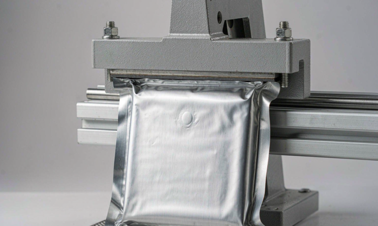
Semi-solid and solid cells are sensitive to mechanical contact. A dendrite is far less likely to nucleate when the electrode stack is held under uniform external pressure, typically between 0.5 and 3 megapascals for our pouch format. Non-uniform pressure creates voids, and voids concentrate current. We use cold isostatic pressing during cell formation to settle the stack before it is sealed, then maintain pressure with a precision compression fixture in the module.
The current collector is the other half of the story. A rough copper foil surface gives lithium more nucleation sites, so we specify a low-roughness electroformed copper with a zirconia or carbon functional coating. We also chamfer and insulate the foil edges, because edge plating is one of the silent killers in stacked cells. Every one of these steps is verified against IEC 62133 mechanical and electrical safety requirements before a cell is released to a customer.
Formation Protocols and Plating Detection
Formation is where dendrites are won or lost. We form semi-solid cells at a low rate, typically 0.1C to 0.2C, and hold the temperature at 25 degrees Celsius. Rushing formation at high rate is the fastest way to hide a plating defect that shows up 200 cycles later. We also run the first formation with a reference electrode in a sample cell so we can watch the anode potential directly rather than inferring it from pack voltage.
For production screening we use two non-destructive checks. The first is electrochemical impedance spectroscopy looking for a growing low-frequency semicircle that signals plating. The second is a differential capacity analysis, dQ/dV, where lithium plating shows up as a distinct shoulder around 0.2 volts versus lithium. If either signal crosses our threshold, the cell is quarantined. These checks feed the same quality gate that qualifies cells for UN38.3 transport testing, so a plating-prone cell never leaves the building.
Cell Architecture and BMS Safeguards
No single material trick replaces good system design. We build in an N/P ratio margin of at least 1.08, meaning the anode has at least 8 percent more lithium capacity than the cathode needs. That margin absorbs uneven stripping and prevents the anode from ever running empty, which is when plating accelerates. For applications like drone battery packs where weight is tight, we trade a small capacity penalty for that safety margin rather than squeezing the anode thin.
The battery management system closes the loop. We set the charge cutoff with a temperature-dependent limit, disable charging below 5 degrees Celsius, and add a plating-aware taper that drops current if cell impedance rises abnormally. For a custom battery solution we also log individual cell voltage deviation; a cell that drifts more than 20 millivolts from the pack mean during charge is flagged for service. Combined with the material and formation work, this is how we ship semi-solid state battery packs that hold their capacity past 1,000 cycles.
At the module level we add redundant voltage taps and a ground-fault monitor so a single dendrite-induced micro-short is isolated before it can propagate. For mobility and aerial platforms this redundancy is non-negotiable, and it is one reason customers choose a purpose-built semi-solid design over a repurposed consumer cell.
What causes lithium dendrites in semi-solid state batteries?
Dendrites are caused by lithium plating during charge, usually triggered by fast charging, low temperature, or an anode that is too thin relative to the cathode. In semi-solid cells the small liquid fraction can concentrate local current and seed filament growth if the interface is not well engineered.
Can semi-solid electrolytes fully prevent dendrite growth?
They reduce the risk substantially compared with liquid electrolytes, but they do not eliminate it. A semi-solid or solid electrolyte raises the mechanical threshold for penetration, yet poor formation, cold charging, or a rough current collector can still nucleate lithium metal. Suppression is achieved through combined material, mechanical, and controls design.
How does formation affect dendrite formation?
Slow, temperature-controlled formation at 0.1C to 0.2C lets lithium deposit uniformly instead of plating. Rushed high-rate formation hides plating defects that surface later as capacity loss or soft shorts. We also screen formation with impedance and differential capacity analysis.
What charging temperature is safe for semi-solid cells?
We disable charging below 5 degrees Celsius and keep formation near 25 degrees Celsius. Below about 5 degrees the anode host diffusion slows so much that lithium plates as metal. A temperature-compensated charge cutoff in the BMS enforces this window.
How do you detect early lithium plating?
We use electrochemical impedance spectroscopy to watch for a growing low-frequency semicircle and differential capacity analysis where plating appears as a shoulder near 0.2 volts versus lithium. Either crossing our threshold quarantines the cell before it ships.
Are semi-solid state batteries safer than liquid lithium-ion?
They are generally safer because the reduced liquid content lowers flammability and the denser electrolyte raises the dendrite penetration threshold. Safety still depends on formation quality, stack pressure, and BMS controls, which is why we validate every design against IEC 62133 and UN38.3.
Further Reading
References