Home Energy Storage Integration for Farms
After twenty years of specifying packs for everything from drone battery fleets to grid-tied cabinets, I have learned that farm projects fail in a completely different way from residential ones. A house is a predictable load behind a predictable service. A farm is an electrical service problem, a motor-starting problem, and a corrosion problem – in that order – and only afterwards a battery problem. I have stood in a milking parlor at 5 a.m. watching a brand-new home energy storage cabinet refuse to start a 7.5 kW well pump that a tired 12 kW diesel genset had started without complaint for fifteen years. The inverter was not defective. It was simply never asked the right question at specification time.
This piece is about integration: the physical and electrical decisions you make to make a storage system actually live on a working farm. It assumes you already know what capacity you want. If you are still at the design stage, read the design and testing articles first, then come back here, because half of what follows will change your bill of materials.
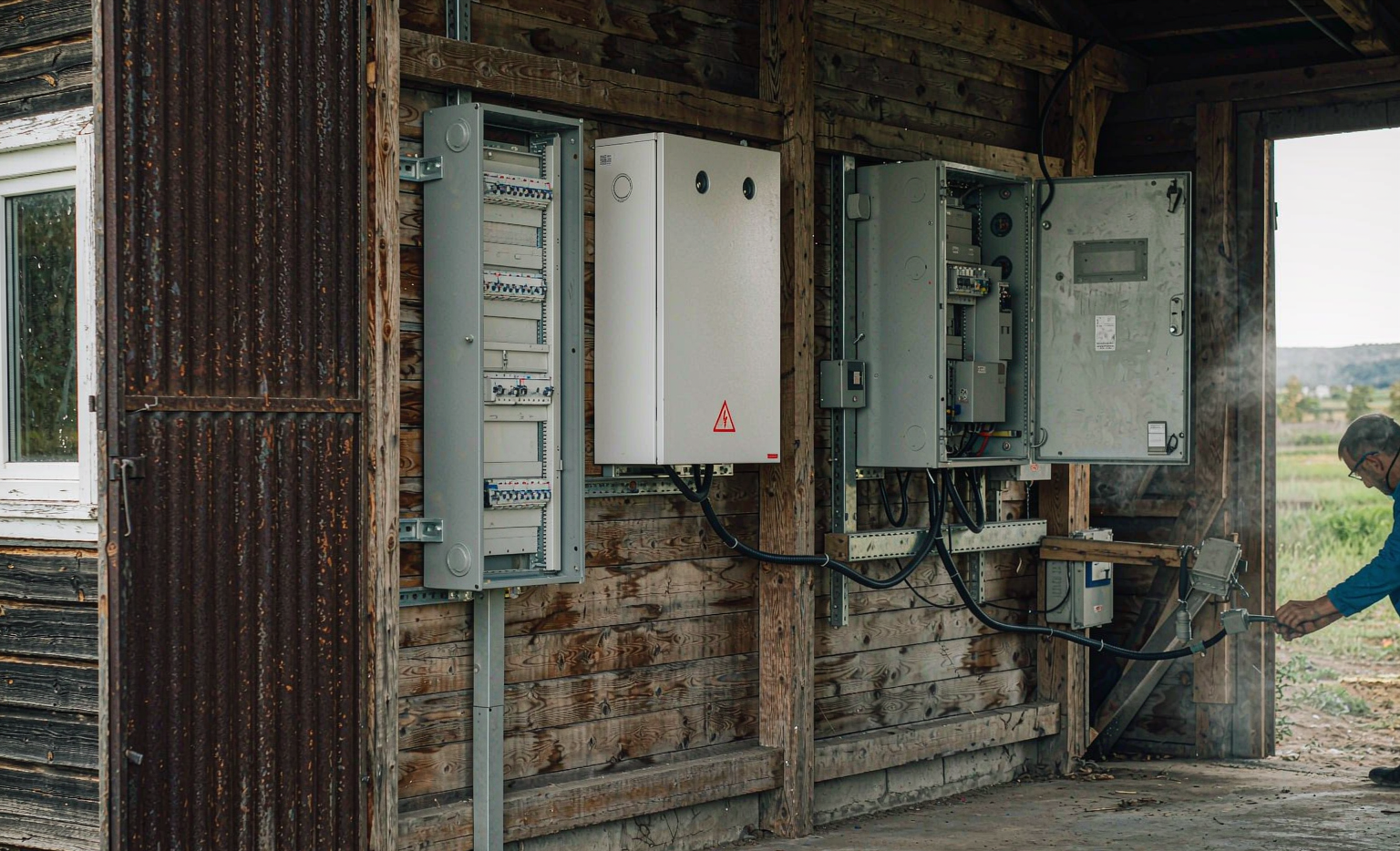
The short version: on a farm, the three things that determine whether your system works are the transformer and service conductors feeding it, the largest motor you must start while islanded, and the air in the room where you put the battery. Get those right and almost any decent lithium pack will be fine. Get them wrong and no amount of software will save you.
Why Farm Integration Is Not Residential Integration
Most home energy storage system products on the market are engineered for a specific fiction: a 120/240 V split-phase service, a 200 A panel in a garage or utility room, a load profile dominated by resistive and small motor loads, and an ambient environment between 5 and 35 degrees Celsius. Every one of those assumptions can break on a farm, and usually at least two of them do.
Here are the four differences that actually matter, in the order they tend to bite:
- The service is weak and long. Rural distribution feeders are long single-phase laterals. Utility voltage at the meter routinely swings 5 to 8 percent between a wet spring and an August irrigation peak, and the available fault current at the service is often a tenth of what it is in town. Your inverter has to ride through that, not fight it.
- Loads are dominated by motors, and motors start at five to eight times running current. This is the number that sizes everything. A 7.5 kW pump is a trivial 30 A running load and a brutal 200 A+ transient.
- The environment is chemically aggressive. Ammonia, hydrogen sulfide, grain dust, and rodents. A barn is classified G3 or GX on the ISA/ANSI 71.04 corrosion severity scale; an office is G1.
- The outage consequences are not convenience. Lost ventilation in a poultry house kills the flock inside an hour. Lost refrigeration or lost milking vacuum costs real money per hour. The backup reserve is a production input, not a comfort setting.
None of these are hard. They are just invisible to anyone who has only ever integrated residential battery storage, and most installers have only ever integrated residential battery storage.
Start at the Service Entrance, Not at the Battery
The first hour of any farm integration job should be spent at the meter and at the transformer, not in the equipment room. Here is what I check.
Service Conductor Length and Voltage Drop
Farm service drops of 60 to 200 m are completely normal. Take a 100 m run of 1/0 aluminum triplex at roughly 0.55 ohm per kilometre per conductor. Round-trip resistance is 100 m x 2 x 0.00055 ohm/m = 0.11 ohm. At 100 A that is 11 V, or about 4.6 percent at 240 V. Add the transformer’s own regulation and you can be at 8 percent before you have turned anything on.
Why it matters for storage: an inverter that sees a soft, sagging grid during irrigation season will hit its undervoltage ride-through limits and disconnect, right when you most want it supporting the load. Some inverters let you widen the acceptable voltage window; on a genuinely weak rural service that adjustment is often legitimate and necessary, but it must be made deliberately, documented, and checked against the interconnection agreement, because grid-support functions such as volt-VAR and ride-through are usually part of the certified settings in IEEE 1547-2018 or EN 50549 and cannot simply be disabled.
Know Your Transformer Connection – Especially High-Leg Delta
This is the single most expensive thing I see people discover late. Rural three-phase service in North America is very often a 120/240 V high-leg delta (also called wild-leg or stinger-leg): two transformers in an open-delta or a closed delta with one winding centre-tapped. You get 240 V between any two phases, 120 V from A or C to neutral, and roughly 208 V from the B phase to neutral.
A single-phase residential-type storage inverter wants to connect across the two legs that are 120 V to neutral – that is, A and C, not A and B. Connect it across the wild leg and every 120 V load on that inverter output sees 208 V, which destroys equipment within seconds. I have seen this happen. It is not a small mistake.
Open-delta service adds a second problem: exporting power into an open-delta bank can produce serious phase imbalance and, in some configurations, ferroresonance and damaging overvoltage on the open corner. If your transformer is an open delta, get the utility’s engineering department on the phone before the interconnection application, and expect a firm answer on whether export is permitted at all. Do not let a salesperson guess.
Transformer Capacity and the One Big Pump Test
Read the kVA on the transformer can. A 25 kVA single-phase transformer at 240 V is 104 A continuous. Now list the loads that can be running simultaneously and add the inrush of the largest motor. If your battery inverter is asked to pass through 60 A of house and barn load while also charging the pack at 40 A and starting a pump at 200 A for two seconds, you are asking a 25 kVA transformer to behave like a 60 kVA one. The voltage dip will trip the inverter, the motor starter, or both.
The fix is almost never a bigger transformer, which is a utility cost with a long lead time. It is usually sequencing: interlock the grain dryer, the water heater, and the workshop circuit so they cannot be energized when the pump starts. A 24 V load-shed relay and a dry contact from the energy management system costs a couple hundred dollars and solves a problem that five thousand dollars of extra inverter capacity does not.
Motor Starting: The Load That Defines the Whole System
If I could only do one calculation on a farm integration project, it would be this one. Everything else is negotiable; this is not.
Read the Nameplate Code Letter, Not Just the Horsepower
NEMA and IEC motors carry a locked-rotor code letter that tells you the starting apparent power per horsepower or per kilowatt. A 10 hp motor with code letter G draws between 5.0 and 5.6 kVA per hp at locked rotor: 50 to 56 kVA. At 240 V single-phase that is 208 to 233 A inrush against a running current of roughly 30 A. A three-phase 7.5 kW motor typically sits at 5 to 7 times full load current, so around 90 to 110 A against 15 A running.
Then read the inverter surge specification with the same suspicion you would read a fuel economy figure. There are three completely different machines hidden behind the phrase “2x surge”:
- 2x for 3 seconds – will start a submersible pump, which has low inertia and comes up to speed fast.
- 2x for 10 seconds – will start a loaded refrigeration compressor or a grain dryer fan fighting static pressure.
- 1.5x continuous for minutes – will start a hammer mill, a loaded auger, or a deep-well turbine pump.
And there is a derating trap that catches even experienced people: surge ratings are almost always quoted into a resistive load at unity power factor. A starting motor runs at 0.3 to 0.5 power factor. The inverter’s semiconductors must supply the real and the reactive components through the same silicon, so the usable surge into a motor is meaningfully lower than the datasheet number. My working rule: take the advertised motor-starting surge and assume it starts a motor about half that size, unless the manufacturer publishes a dedicated motor-starting curve or a horsepower table. If they publish a horsepower table, use it – it is the only honest number in the document.
Soft Starters, VFDs, and Why a Drive Changes Everything
The correct answer to “the pump trips my inverter” is rarely a bigger inverter. It is usually a drive.
- Soft starter: reduces inrush to roughly two to three times full load current by ramping voltage. Cheap, effective, and it must have a bypass contactor once the motor is up to speed or you will cook the thyristors. It also injects harmonics during the ramp, which some inverters dislike.
- Variable frequency drive: inrush drops to 1.0 to 1.5 times rated, the ramp is programmable, and you get a second enormous benefit on pumps – a soft ramp eliminates water hammer, which is what actually splits submersible pump columns and blows apart old galvanized lines. If you have ever heard a bang in the pump house when the pump kicks off, you have water hammer.
- Single-phase input VFDs: these let you run a three-phase motor from a single-phase farm service, which for many farms eliminates the entire three-phase problem. The caveat: derate the drive roughly 50 percent for single-phase input, so a 7.5 kW motor needs a 15 kW frame. Buy the frame, not the number on the motor.
A 7.5 kW submersible irrigation pump on a VFD is a completely different animal from the same pump across the line: 30 A running, about 36 A starting, and it can be ramped over 5 to 10 seconds so that the inverter barely notices. Add a 3 kW milking vacuum pump and 2 kW of refrigeration, and a 12 kW continuous inverter with a modest surge becomes a viable design – where the same loads across the line would have needed 25 kW.
Three-Phase Loads on Single-Phase Service
Centre pivots, grain dryers, and larger augers are frequently three-phase, and the farm service is frequently single-phase. Three routes exist:
- Rotary phase converter: cheapest capital cost, worst behaviour with an inverter. It must be started unloaded, its inrush is its own event, the manufactured leg runs hot and out of balance, and the resulting current imbalance is exactly what a single-phase inverter handles worst. If you already have one, plan for it carefully or replace it.
- VFD with single-phase input: my default recommendation for a single large motor such as a pivot pump.
- Three-phase hybrid inverter or a dedicated three-phase ESS: the right answer when you have multiple three-phase loads. It costs more and it moves you out of residential battery storage product categories entirely into commercial equipment, which brings different certification and installation requirements.
Batteries and Generators Do Different Jobs
Almost every farm I visit already has a genset, and the instinct is to replace it. Usually the right answer is to keep it and give it a narrower job.
A diesel genset is genuinely better than an inverter at motor starting – rotating inertia gives it a real 3x for 10 seconds capability – and genuinely worse at light load, where running below about 30 percent of rated kW causes wet stacking, carbon buildup, and shortened engine life. So let each machine do what it is good at. The architecture I recommend:
- The battery carries the continuous base load silently, which is 90 percent of farm outage hours.
- The genset starts on a dry contact (SoC below 30 percent, or a predicted large motor start, or a long-outage timer) and runs at a healthy 50 to 70 percent load to recharge the pack and cover peaks.
- Charge current is capped as a percentage of the genset’s continuous kW – I use 70 to 80 percent of the rectifier’s total demand budget – so the engine is never asked to charge at full rate and start a pump at the same moment.
- When the pack is full, the genset shuts down. A farm outage that would have burned 40 litres of diesel now burns 8.
Where the Inverter Couples: Zones, Not Whole-Farm Backup
Whole-farm backup on a working farm is usually the wrong target. Sizing an inverter to start a 50 hp pivot pump means buying a machine that idles at 3 percent load for 8,700 hours a year, which is terrible for efficiency and terrible for economics.
Instead, split the farm into three zones at the panelboard level:
- Zone 1 – always backed up. Dwelling essentials, milking parlor, bulk tank refrigeration, stock water pumps, ventilation controls, communications, and the drone battery charging station for the agricultural spraying fleet. On most farms this is 3 to 8 kW continuous.
- Zone 2 – backed up when energy is available. Workshop, welder, grain handling, EV charger, irrigation booster. Controlled by a load-shed contactor.
- Zone 3 – never backed up. Electric grain dryer elements, shop heaters, the big pivot pump. Wire these ahead of the backed-up panel so they simply do not exist during an outage.
Ventilation Is Life Safety, and That Changes the Transfer Time
In a poultry or swine building, ventilation failure is a mortality event, not a comfort event. In summer, a fully stocked house can reach lethal temperatures in well under an hour. So ventilation goes in Zone 1 – and then a subtle detail bites you.
Motor contactors drop out at roughly 60 to 70 percent of nominal voltage and will release within one or two cycles of a transfer. A fan motor itself will coast through a one or two second interruption without stalling, but its starter will have dropped out, and nothing will bring it back. The result is the failure mode nobody expects: the outage is handled perfectly, the inverter is online, and the fans are off because their contactors released and never re-energized.
Three fixes, in order of preference: specify a fast transfer (under 20 ms) so the contactor never sees the interruption; or use a starter with a time-delayed dropout / automatic restart on power restoration; or supply the starter control circuit from a small always-on UPS. Confirm which one you have before you leave site, by actually opening the main breaker and watching the fans.
Making the Battery and the Generator Coexist
Two rules, both of which have destroyed equipment when ignored:
- The inverter must be told to stop when the genset runs. A grid-forming inverter that sees a stable 50 or 60 Hz source will happily try to export into a generator. The generator’s AVR then fights the inverter, and the usual outcome is that the inverter trips, the generator’s AVR or windings are stressed, or both. Every credible hybrid inverter has a dedicated generator input, a dry contact to enable it, or a zero-export current transformer. Commission it and test it.
- The genset must see minimum load. Below about 30 percent rated kW, diesels wet stack. If your transfer scheme leaves the genset idling at 2 kW, add a load bank or raise the charge rate so it always sees a real load.
AC Coupling Versus DC Coupling on a Farm Layout
Farms are spread out, and that decides this question. If you already have a microinverter array on a barn roof 80 m from the house, AC coupling is almost always the right retrofit: you leave the solar alone, put the battery and inverter near the house, and let them communicate over the existing AC wiring. If the solar is new and co-located with the battery, DC coupling wins on efficiency and on the ability to charge directly during an outage when the grid is down and the sun is up – which for a farm is often the difference between a four hour and a two day outage.
The Barn Environment: What Kills Equipment in Three Years
This is the section I wish every farm integration quote included, because it is where the cheap installations quietly die.
Ammonia and Hydrogen Sulfide Are Electronics Solvents
Livestock buildings run 10 to 25 ppm of ammonia routinely and much higher during litter cleanout. Manure pits and agitation events produce hydrogen sulfide peaks of 100 to 400 ppm. Hydrogen sulfide attacks silver – resistor terminations, contact surfaces, plating – forming silver sulfide. Ammonia complexes with copper. The result is creeping contact resistance and intermittent faults that no diagnostic software will ever name.
The industry has a scale for this: ISA/ANSI 71.04 defines severity levels G1 (mild), G2 (moderate), G3 (harsh), and GX (severe), with copper and silver coupon corrosion rates measured over 30 days. An office is G1. A dairy barn, poultry house, or swine building is G3 and sometimes GX. Most residential storage equipment is built for G1.
If the equipment must live in a corrosive atmosphere, ask for: conformal coating to IPC-CC-830 (acrylic AR or urethane UR at 25 to 75 micrometres), sealed relays rather than open-frame, no exposed silver-plated contacts, nickel-plated or coated busbars, a gasketed IP54 minimum enclosure (IP65 preferred), and a desiccant breather or filtered positive-pressure vent so the room air does not freely exchange with the cabinet.
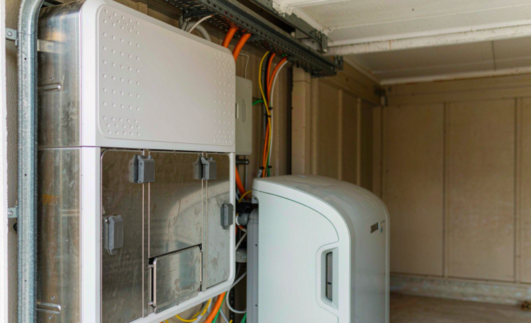
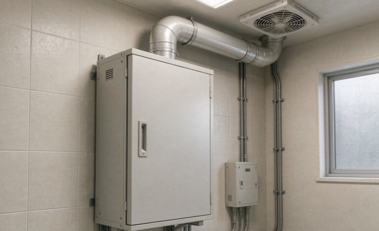
And now the advice that saves the most money: do not put the battery in the animal building at all. Put it in a separate, clean, ventilated utility room or a purpose-built enclosure outside. The barn has space, which is exactly why everyone puts it there, and it is the most expensive free space on the property.
Dust, and the Fact That Grain Dust Is Combustible
Grain dust is not just dirt, it is a fuel. Grain handling areas are classified environments – Class II Division 2 under the NEC, Zone 22 under IEC 60079-10-2, with NFPA 61 covering the facility practice. A standard vented enclosure with a fan is, functionally, a dust collector with electronics inside it. Filtered vents are mandatory, and filters clog, so put filter replacement on the annual maintenance schedule with a date and a name next to it.
Rodents Chew Your Arc-Flash Protection
Mice pass through a 6 mm gap. They travel in ceiling voids and along the warm top of equipment, and they chew cable insulation. A chewed DC conductor with a 400 V potential behind it is an arc fault waiting for a damp morning. Requirements: full metal conduit or metal-clad cable for the entire DC run, every penetration sealed with a listed fitting plus copper mesh or wool, no exposed cable in the void above a drop ceiling, and a look at the tray every spring.
Temperature: The Cold Charging Limit Is Not a Suggestion
An unheated shed in a continental climate swings from minus 30 to plus 40 degrees Celsius. Two facts follow.
First, an LFP cell cannot accept charge below 0 degrees Celsius. Below that, lithium plates onto the anode as metal instead of intercalating, and that is permanent capacity loss and a nucleation site for dendrites. This is not a performance degradation you can tune away; it is a hard electrochemical limit. If your shed goes below freezing, you need either an integrated self-heating pack or an enclosure heater on the backed-up panel – and budget the heating energy, because bringing a 10 kWh pack from minus 20 degrees to a chargeable temperature takes roughly 1 to 2 kWh of energy you paid for and will not get back.
Second, heat accelerates aging. The usual engineering rule of thumb is that calendar aging roughly doubles for every 10 K above 25 degrees Celsius. A well-sealed grey box in direct summer sun can reach 60 to 70 degrees internally. Shade, a reflective roof, or a thermostatically controlled fan is not an accessory; at those temperatures it can literally halve the service life of the pack.
Lightning, Grounding, and One Electrode System
Rural overhead services, tall silos, and long buried runs to pivots make farms lightning-prone. Fit Type 1 and Type 2 surge protective devices at the service and at the subpanel, plus a DC-side SPD on long runs. And bond everything to one ground electrode system. Driving a separate rod for the battery cabinet is a common and dangerous piece of folk practice: it creates a step and touch potential hazard during a strike and it gives the surge a path straight through your electronics on the way to the other rod.
Stray Voltage and the Equipotential Plane
Dairy cattle are far more sensitive to small AC voltages than people are; behavioural and production effects are reported at a volt or two and a few milliamps. Electrical codes for agricultural buildings respond to this with an equipotential plane requirement – in North America, NEC 547.10 requires bonding of all metal and the reinforcing steel in the floor of livestock confinement areas.
A storage system introduces a new source and, critically, a new neutral-to-ground bonding behaviour when it islands. So the integration checklist must include a measurement: with the system in grid mode and again in island mode, measure the voltage across the equipotential plane and across the cow contact points. If the inverter switches the N-G bond on transfer, the two numbers should agree. I have seen a system that was electrically perfect and behaviourally terrible for the herd, and the fix was a bonding change, not a battery change.
Distance, Siting, and Where to Put the Cabinet
Farm layouts spread loads over tens to hundreds of metres, and that drives topology.
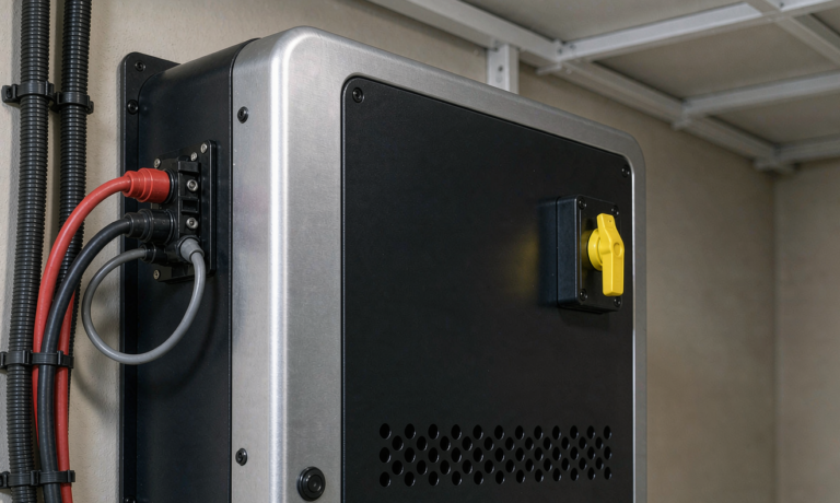
Keep DC runs short. At a 48 V nominal bus, 5 kW is about 104 A. To carry that 30 m at a 1 percent drop you would need cable that costs more than the inverter. The rule I use: DC runs under 10 m, inverter adjacent to the battery, and run AC for anything long. Where the power is higher, a 400 V battery architecture cuts current by roughly tenfold and makes long runs feasible – which is one of the reasons larger farm systems migrate up in voltage.
Separate structures need separate treatment. If the battery lives in the barn and feeds the house, that is a feeder to another structure. It requires its own grounding electrode system, a disconnecting means at the building, and an equipment grounding conductor that runs with the feeder conductors. Do not reuse a water pipe or a fence as the electrode, and do not create a second neutral-to-ground bond.
Siting rules I apply without exception: never in an animal building; never in the fertilizer or chemical store, where ammonium nitrate and urea dust are both corrosive and oxidizing; never below the grain dryer exhaust; above the local flood line; out of the swing path of a loader bucket; with the code-required working clearance in front (roughly 0.9 m and the full width of the equipment); and on a wall or pad that will not be hit by a pressure washer.
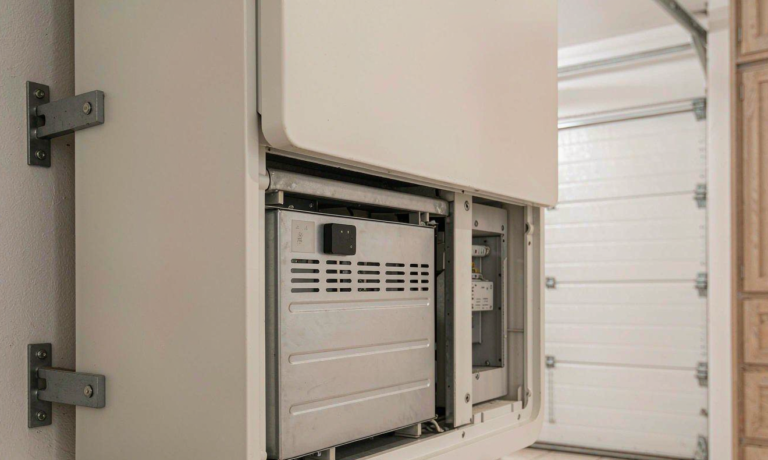
One more from experience: think about how a 90 kg module gets up a barn ladder and through a 750 mm doorway before you buy it. Modular, two-person-carryable enclosures have saved more farm projects than any electrical feature I can name.
Tariffs, Interconnection, and the Economics of Integration
Know the Tariff Before You Size Anything
Agricultural tariffs are not residential tariffs. The features that change your design:
- Demand charges in kW. A battery that shaves the peak set by a grain dryer or a pivot pump can produce savings that dwarf energy arbitrage. Look at your highest fifteen-minute demand of each month before anything else.
- Time-of-use windows that do not match your work. Irrigation is often scheduled by water rights and crop need, not by price. A TOU-optimized schedule that assumes you can move the load may be fiction.
- Low or zero export credit. On many rural tariffs, exported energy is worth a fraction of imported energy or nothing. If export is worthless, self-consumption maximization is the only strategy that pays, and a smaller battery may be the better investment.
- Load control or ripple control receivers. Some irrigation rates give a discount in exchange for the utility’s ability to switch off your pump at peak. Find out whether your battery’s controller and charger sit on the controlled circuit. If they do, you can end up charging at the controlled rate and discharging into uncontrolled loads, which most utilities treat as a tariff violation.
Export Limits and the Zero-Export Loop
Rural feeders frequently have no hosting capacity left. Expect one of three outcomes from the interconnection application: full export, capped export (5 kW, or 15 percent of inverter rating, are common), or zero export. Zero export requires current transformers at the service and a control loop fast enough to follow your largest load step – if the response is slow, your barn load dropping suddenly becomes an export event and you trip on reverse power. Ask the manufacturer for the control loop response time in writing, then verify it on site by switching off a large load while the sun is up.
The State-of-Charge Conflict Nobody Flags
An arbitrage-optimized controller wants to empty the pack by morning to capture the peak spread. A backup system must hold a reserve. These two objectives are in direct conflict, and the default configuration on most products favours arbitrage, because that is what shows up in the savings report.
On a farm, set the reserve first and treat it as a production input. Work backwards from the design event: the critical zone load multiplied by the hours you must survive. Eight hours at 3 kW is 24 kWh usable; at 90 percent depth of discharge and 90 percent round-trip efficiency, that is roughly 30 kWh of nameplate capacity. Write the number down, configure it as a floor, and let the optimizer use only what sits above it. I have lost count of the systems I have found at 100 percent depth of discharge schedules with nothing left when the storm arrived.
Codes, Standards, and What the Inspector Will Actually Ask For
The paperwork list for a farm installation is longer than for a house, mostly because of the agricultural building rules. What I assemble:
- Cells and packs: IEC 62133-2 or UL 1642 at cell level, IEC 62619 or UL 1973 at pack level, UN38.3 test summary for transport (publicly available since 2020 for anyone who asks).
- Installation: IEC 62485-2 or UL 9540 with UL 9540A thermal runaway propagation data; NFPA 855 for spacing, separation, and detection. Small residential-scale systems are often exempt from parts of NFPA 855 – confirm the exemption with the authority having jurisdiction in writing before you order, not after.
- Grid interconnection: IEEE 1547-2018 with UL 1741 SA or SB certification in North America; EN 50549, G98 or G99 in the UK and Europe; AS/NZS 4777.2 in Australia and New Zealand.
- General installation: NEC 480 (storage), 690 (PV), 705 (interconnected systems), and 702 or 706 depending on architecture. For agricultural buildings specifically, NEC 547 is the one installers miss: 547.5 restricts wiring methods in damp and corrosive locations, 547.8 addresses dusttight and watertight enclosures and corrosion protection, and 547.9 covers the equipotential plane and bonding of all metal. The IEC equivalent is IEC 60364-7-705, which requires IP44 as a floor (IP54 in practice), RCD protection, and specific earthing arrangements for livestock areas.
Commissioning Checklist
Twelve items, each of which has caught a real fault on a farm job:
- Verify the transformer connection type and phase-to-neutral voltages at the meter before energizing anything.
- Confirm the inverter’s acceptable voltage and frequency window against the measured service, and document any widening.
- Test every motor start while islanded, one at a time and then in the worst realistic combination, with a clamp meter capturing peak current.
- Verify load-shed and sequencing interlocks actually prevent the prohibited combinations.
- Force a transfer with ventilation running and confirm the fans keep running, not just the inverter.
- Test generator mode: inverter export blocked, minimum genset load satisfied, charge current capped, and auto shutdown on full.
- Test zero-export operation by switching off your largest load on a sunny day.
- Measure insulation resistance on the DC side and record the baseline.
- Torque audit with a calibrated wrench on every DC and AC termination, with torque marks.
- Measure voltage across the equipotential plane in both grid and island modes.
- Confirm enclosure IP rating, filter condition, breather installation, and rodent sealing at every penetration.
- Deliver the documentation package: single-line diagram, torque schedule, baseline DCIR and capacity traces, commissioning test results, and monitoring account credentials transferred to the owner’s name, not the installer’s.
When a custom battery solution Is Actually Worth It
I am not going to tell every farmer they need custom equipment, because most do not. A catalog home energy storage battery unit is the right answer when your service is ordinary 120/240 V split phase, your equipment room is dry and clean, your critical loads fit on a single 40 A subpanel, and your largest motor is under about 2 kW. In that case, buy the catalog product and spend the savings on a VFD for the pump.
A custom battery solution earns its cost when at least two of the following are true:
- Your service is high-leg delta, 400 V three-phase, or an open delta with an export restriction.
- You must start a 7.5 kW or larger motor from batteries while islanded, and you need a documented motor-starting capability rather than a marketing surge number.
- The array or the load is more than 50 m from the battery, and you need a higher DC bus voltage to make the run efficient.
- The environment is G3 or GX corrosive, combustible dust classified, or routinely below freezing, and you need coated boards, sealed enclosures, and an integrated heater with a defined setpoint.
- You need the BMS’s dry contacts mapped to a specific generator ATS, irrigation controller, and ventilation alarm, with a defined alarm ladder rather than a single common fault.
- You need modules sized so that two people can carry them through a narrow doorway and up a ladder.
That last point deserves emphasis, because it is where good battery pack design shows up on a farm. The electrical design is the part everyone argues about. The mechanical design – module weight, carry handles, connector orientation, and whether you can service the BMS without removing the whole cabinet from the wall – is the part that determines whether the system is still being maintained properly in year eight.
Frequently Asked Questions
Can I run a three-phase irrigation pivot from a home energy storage system?
Not from a single-phase residential unit, and I would not try. Either use a VFD with single-phase input on the pivot’s motor, derated about 50 percent for the single-phase supply, or move to a three-phase storage inverter sized for the pump’s starting current. If the pivot is the only three-phase load, the VFD is almost always the cheaper and more robust answer, and it gives you soft-start and speed control for water application rate as a bonus.
Why does my pump trip the inverter when the inverter rating is higher than the pump’s kilowatts?
Because the pump’s running current is not the design number – its locked-rotor current is. A 7.5 kW pump can pull 200 A or more for a second or two, and your inverter’s surge rating is quoted into a resistive load at unity power factor, not into a motor at 0.3 to 0.5 power factor. Fit a VFD or soft starter, or buy an inverter with a published motor-starting table. Adding more inverter capacity is the most expensive way to solve this.
Should I install the battery in the barn because it has plenty of space?
No, not if the barn houses animals. Ammonia and hydrogen sulfide put the environment at G3 or GX on the ISA/ANSI 71.04 scale, and most storage equipment is built for G1. Use a separate clean, ventilated utility room or an external enclosure. If the animal building is genuinely the only option, you need conformal-coated electronics, sealed relays, IP65, and a filtered or positive-pressure vent – and you should still expect a shorter service life.
Can I keep my existing diesel generator?
Almost always yes, and you usually should. The genset is better at motor starting than an inverter, and the battery is better at carrying light load for hours. Wire a dry contact from the BMS or energy manager to the genset’s start input, cap charge current at 70 to 80 percent of the engine’s continuous output, and let the battery handle the quiet hours. Typical result: diesel consumption during outages drops by 70 to 80 percent.
How do I stop the battery back-feeding the generator or the grid during an outage?
For the generator, use the inverter’s dedicated generator input, its enable dry contact, or a zero-export CT at the generator output, and then test it by running the genset with the battery charged and a light load. For the grid, the requirement is certified anti-islanding under IEEE 1547-2018, EN 50549, or the applicable local rule, plus a listed transfer mechanism. Never rely on a manual procedure for this – the one time someone forgets is the time a line worker gets hurt.
Do I need a separate ground rod for the battery cabinet in the shed?
No. Separate rods create step and touch potential hazards and give lightning surge a destructive path between the two electrodes. Bond the equipment to the existing grounding electrode system. If the battery is in a separate structure feeding another building, that structure needs its own electrode system and its own disconnect, but the equipment grounding conductor must run with the feeder and you must not create a second neutral-to-ground bond.
Will a battery system fix my stray voltage problem?
It will not fix an existing problem, and it can create one. If the inverter switches the neutral-to-ground bond when it islands, the equipotential plane voltage can change between grid and island modes. Measure across the plane in both modes with a high-impedance meter and a 500 ohm resistor loading, and correct the bonding arrangement if the numbers move. In some cases a storage system genuinely helps, by letting you isolate a problematic circuit, but that is a diagnosis, not an assumption.
How big should my backup reserve be?
Work backwards from the design event rather than forwards from a percentage. Multiply the critical-zone load in kilowatts by the hours you must survive and divide by usable capacity. Eight hours at 3 kW is about 24 kWh usable, which is roughly 30 kWh of nameplate capacity at 90 percent depth of discharge and 90 percent round-trip efficiency. Decide whether your design event is a four-hour afternoon storm or a two-day winter ice outage – on a farm those are very different systems.
Does cold weather ruin a lithium battery?
Discharging in the cold is fine within limits; charging below freezing is what causes permanent damage, because lithium plates onto the anode as metal instead of intercalating. If your equipment room can drop below 0 degrees Celsius, you need a self-heating pack or an enclosure heater on the backed-up circuit. Budget the heating energy: bringing a cold 10 kWh pack up to a chargeable temperature can consume 1 to 2 kWh of your own stored energy.
Is a sodium-ion battery a better fit for a cold farm shed?
It can be. Sodium-ion chemistry generally tolerates low-temperature charging better than LFP and is comfortable at deeper discharge, and for a stationary application where volumetric energy density barely matters, that trade is attractive. The practical obstacle at the moment is product availability and certification for grid-connected residential use in most markets. If you have a genuinely unheated site and no economic way to condition it, it is worth asking about – but verify that the specific product carries the interconnection certification your utility requires.
Do I need to worry about the charging station for my agricultural drones?
Yes, and it is usually forgotten. A spraying fleet with four to six packs on fast charge is a real 2 to 3 kW schedulable load that lands in a predictable window. Because it is schedulable, it is actually one of the friendliest loads on the property: put it in Zone 2, let the energy manager run it when the pack is full and the sun is up, and it costs you almost nothing. It belongs on the critical load list when spraying is time-critical to the crop.